Download
1 / 14
140 likes | 469 Vues
Project Title. PRE-STAMPEDE MONITERING AND ALARM SYSTEM Under the Guidance of Submitted by. ABSTRACT.

E N D
Project Title PRE-STAMPEDE MONITERING AND ALARM SYSTEM Under the Guidance of Submitted by
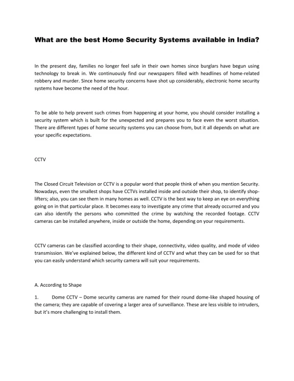
ABSTRACT This project will help us develop a pedestrian flow prediction and risk management system in most of pilgrimage places, in buses and may apply to many other shopping districts. In this project development process, number of push button are set, depending upon the number of switches pressed by the pedestrians will give an signal to a programmable microcontroller of 8051 family conducts the transistor and in turn buzzer sounds indicating the pedestrians are crowded. The status is displayed on the LCD.
HARDWARE REQUIREMENTS • TRANSFORMER (230 – 12 V AC) • VOLTAGE REGULATOR (LM 7805) • RECTIFIER • FILTER • PIC Microcontroller (16F877A) • LED • PUSH BUTTONS • BUZZER • BC547 • 1N4007 • RESISTOR • CAPACITOR
POWER SUPPLY Bridge rectifier 5v Regulator 230 V AC 50 Hz 5V DC Filter(470µf) 12V step down transformer
High-Performance RISC CPU: Only 35 single-word instructions. All single-cycle instructions except for program branches, which are two cycle. Operating speed: DC – 20 MHz clock input DC – 200 ns instruction cycle Up to 8K x 14 words of Flash Program Memory, Up to 368 x 8 bytes of Data Memory (RAM), Up to 256 x 8 bytes of EEPROM Data Memory. Pin out compatible to other 28-pin or 40/44-pin, PIC16CXXX and PIC16FXXX microcontrollers. PIC (PIC16F877A)
100,000 erase/write cycle Enhanced Flash program memory typical. 1,000,000 erase/write cycle Data EEPROM memory typical. Data EEPROM Retention > 40 years. Self-reprogrammable under software control. In-Circuit Serial Programming™ (ICSP™) via two pins. Single-supply 5V In-Circuit Serial Programming. Watchdog Timer (WDT) with its own on-chip RC oscillator for reliable operation. Programmable code protection. Power saving Sleep mode. Selectable oscillator options. In-Circuit Debug (ICD) via two pins. Special Microcontroller Features:
Timer0: 8-bit timer/counter with 8-bit prescaler. Timer1: 16-bit timer/counter with prescaler, can be incremented during Sleep via external crystal/clock. Timer2: 8-bit timer/counter with 8-bit period register, prescaler and postscaler. Two Capture, Compare, PWM modules - Capture is 16-bit, max. resolution is 12.5 ns - Compare is 16-bit, max. resolution is 200 ns - PWM max resolution is 10-bit Synchronous Serial Port (SSP) with SPI™ (Master mode) and I2C™ (Master/Slave). Universal Synchronous Asynchronous Receiver Transmitter (USART/SCI) with 9-bit address detection. Parallel Slave Port (PSP) – 8 bits wide with external RD, WR and CS controls (40/44-pin only). Brown-out detection circuitry for Brown-out Reset (BOR). Peripheral Features:
LEDS LEDs are semiconductor devices are made out of silicon,When current passes through the LED, it emits photons as a byproduct. Normal light bulbs produce light by heating a metal filament until its white hot LEDs present many advantages over traditional light sources including lower energy consumption, longer lifetime, improved robustness, smaller size and faster switching
BUZZER • Piezo Buzzer • This buzzer is an piezo type audio signaling device, which has a piezo • element and a oscillating circuit inside which oscillates the piezo brass base • plate, which when given voltage difference produces sound of a predefined • frequency. • Features • These high reliability piezo buzzers are applicable to general electronics equipment. • Compact, pin terminal type Piezo buzzer with 4 KHz output. • Pin type terminal construction enables direct mounting onto printed circuit boards.
BC547 • The BC547 transistor is an NPN Epitaxial Silicon Transistor. • The BC547 transistor is a general-purpose transistor in small plastic packages. • It is used in general-purpose switching and amplification BC847/BC547 series 45 V, 100 mA NPN general-purpose transistors. • Whenever base is high, then current starts flowing through base and emitter and after that only current will pass from collector to emitter