Download

1 / 53
530 likes | 558 Vues
Learn the fundamentals of UML Class Diagrams, Associations, and Class Modeling in software engineering. Explore different UML diagrams, symbols, and essential techniques for developing effective class models.

E N D
CIE 203 Software Engineering Lecture 8: Class Modeling I Mohammad El-Ramly, PhD 2016 Read Chapter 5 from OO SE 2/e, Slides by: Timothy Lethbridge
Last Lecture • Use cases • Techniques for gathering • requirements • Types of requirements document • Reviewing requirements Chapter 5: Modelling with classes
Outline • What is UML? • UML Class Diagrams • Associations • Generalization • Aggregations Chapter 5: Modelling with classes
5.1 What is UML? • The Unified Modelling Language is a standard graphical language for modelling object oriented software • Developed byRumbaugh, Booch, Jacobson • They founded Rational Software Corporation, later bought by IBM • In 1997 the Object Management Group (OMG) started the process of UML standardization Chapter 5: Modelling with classes
UML diagrams • Class diagrams (static view) • describe classes and their relationships • Interaction diagrams (dynamic view) • Sequence and communication diagrams • Show the behaviour of systems in terms of how objects interact with each other Chapter 5: Modelling with classes
UML diagrams • State diagrams and activity diagrams • show how systems or classes behave internally • Component and deployment diagrams • show how the various components of systems are arranged logically and physically Chapter 5: Modelling with classes
5.2 Essentials of UML Class Diagrams • The symbols on class diagrams are: • Classes • represent the types of data themselves • Attributes • are simple data found in classes and their instances • Operations • represent the abstractfunctions performed by the classes and the specific methods implementing them Chapter 5: Modelling with classes
5.2 Essentials of UML Class Diagrams • The symbols on class diagrams are: • Associations • represent linkages between instances of classes • Generalizations • group classes into inheritance hierarchies Chapter 5: Modelling with classes
Classes • A class is simply represented as a box with the name of the class inside • The diagram may also show the attributes and operations • The complete signature of an operation is: operationName (parameterName: parameterType …): returnType Chapter 5: Modelling with classes
Classes Chapter 5: Modelling with classes
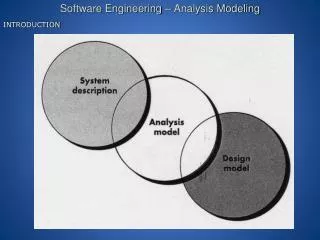
Developing Class Models • Class diagrams used for different purposes during different times in the development life-cycle • Models that support earlier modeling: • For domainanalysis • For requirementsspecification • Models that are close to code • Class diagrams developed iteratively • Details added over time during lifecycle
Design and Code Level Perspectives • What’s useful at the design level? • Your thoughts here:
Implementation Level Class Diagrams • Implementation • Direct code implementation of each class in the diagram • A blue-print for coding • Practical issue: How much detail? • getters and setters? • library classes like String? • Reverse- and round-trip engineering tools
5.3 Associations and Multiplicity • Anassociation is used to show how two classes are related to each other • Symbols indicating multiplicity are shown at each end of the association Chapter 5: Modelling with classes
5.3 Associations and Multiplicity Chapter 5: Modelling with classes
Labelling Associations Chapter 5: Modelling with classes
Analyzing and validating associations • Many-to-one • A company has many employees, • An employee works only for 1 company • A company can have zero employees • E.g. a ‘shell’ company • It is not possible to be an employee unless you work for a company * 1 worksFor Employee Company Chapter 5: Modelling with classes
Analyzing and validating associations • Many-to-many • An assistant can work for many managers • A manager can have many assistants • Assistants can work in pools • Managers can have a group of assistants • Some managers might have 0 assistants. • Is it possible for an assistant to have, perhaps temporarily, zero managers? 1..* * Assistant Manager Open in Umple supervisor Chapter 5: Modelling with classes
Analyzing and validating associations • One-to-one • For each company, there is exactly one board of directors • A board is the board of only 1company • A company must always have a board • A board must always be of some company 1 Board of Directors 1 Company Chapter 5: Modelling with classes
Analyzing and validating associations • Avoid unnecessary 1-to-1 associations • Avoid this do this Chapter 5: Modelling with classes
A more complex example • A booking is always for exactly one passenger • no booking with zero passengers • a booking could never involve more than one passenger. • A Passenger can have any number of Bookings • a passenger could have no bookings at all • a passenger could have more than one booking Chapter 5: Modelling with classes
Association classes • Sometimes, an attribute that concerns 2 associated classes cannot be placed in either of the classes • The following are equivalent Open in Umpleandextended example Chapter 5: Modelling with classes
Reflexive associations • It is possible for an association to connect a class to itself Open in Umple Chapter 5: Modelling with classes
Directionality in associations • Associations are by default bi-directional • It is possible to limit the direction of an association by adding an arrow at one end Open in Umple Chapter 5: Modelling with classes
5.4 Generalization • Specializing a superclass into two or more subclasses • A generalization set is a labeled group of generalizations with a common superclass • The label (sometimes called thediscriminator) describes the criteria used in the specialization Chapter 5: Modelling with classes
5.4 Generalization Chapter 5: Modelling with classes
Handling multiple discriminators • Creating higher-level generalization Chapter 5: Modelling with classes
Handling multiple discriminators • Using multiple inheritance Chapter 5: Modelling with classes
Avoiding having instances change class • An instance should never need to change class Chapter 5: Modelling with classes
CS251: Course prerequisite CS352: Course successor Chapter 5: Modelling with classes
5.5 Object Diagrams • A link is an instance of an association • In the same way that we say an object is an instance of a class Chapter 5: Modelling with classes
Associations versus generalizations in object diagrams • Associations describe the relationships that will exist between instances at run time. • When you show an instance diagram generated from a class diagram, there will be an instance of both classes joined by an association Chapter 5: Modelling with classes
Associations versus generalizations in object diagrams • Generalizations describe relationships between classes in class diagrams. • They do not appear in instance diagrams at all. • An instance of any class should also be considered to be an instance of each of that class’s superclasses Chapter 5: Modelling with classes
5.6 More Advanced Features: Aggregation • Aggregations are specialassociations that represent ‘part-whole’ relationships. • The ‘whole’ side is often called the assembly or the aggregate • This symbol is a shorthand notation association named isPartOf Chapter 5: Modelling with classes
When to use an aggregation • As a general rule, you can mark an association as an aggregation if the following are true: • You can state that • the parts ‘are part of’ the aggregate • or the aggregate ‘is composed of’ the parts • When something owns or controls the aggregate, then they also own or control the parts Chapter 5: Modelling with classes
Composition • A composition is a strong kind of aggregation • if the aggregate is destroyed, then the parts are destroyed as well Chapter 5: Modelling with classes
Composition • Two alternatives for addresses Chapter 5: Modelling with classes
Aggregation hierarchy Chapter 5: Modelling with classes
Propagation • A mechanism where an operation in an aggregate is implemented by having the aggregate perform that operation on its parts • At the same time, properties of the parts are often propagated back to the aggregate Chapter 5: Modelling with classes
Interfaces • An interface describes a portion of the visible behaviour of a set of objects. • An interface is similar to a class, except it lacks instance variables and implemented methods Chapter 5: Modelling with classes
Example: Problem Report Tool • A CASE tool for storing and tracking problem reports • Employees are either developers or managers. • Each developer has a manager. • Each project is assigned a manager and a number of developers. • A developer and a manager may be assigned to more than one project or to no project.
Example: Problem Report Tool • A CASE tool for storing and tracking problem reports • A project consists of artifacts (domain analysis, SRS, code, test cases, etc.) • Problem reports can be made on any artifact of a project to describe an error in it. • Each report contains a problem description and a status • Each problem can be assigned to someone by the project manager.
Example: Problem Report Tool • A CASE tool for storing and tracking problem reports • A problem report has history entries, each describe an action or update made on the issue described in the problem report. • A special kind of reports is code or bug reports, which include additional information about the location of the bug in code, the circumstances that made it appear, the test cases that failed, etc.