Download
1 / 49
490 likes | 508 Vues
Learn about the system architecture of GSM, a second-generation cellular system, utilizing a network of cells to mitigate fragmentation issues. Explore GSM subsystems, including mobile stations, BTS, BSC, TRAU, MSC, HLR, VLR, and EIR, forming a comprehensive PLMN. Understand the functionality and communication channels within a GSM network.

E N D
Global System for Mobiles Lecture 4
Global System for Mobiles • A second generation cellular system • Dev to solve the fragmentation problems of Ist generation cellular systems in Europe • World’s most popular 2G technology that specified digital modulation and network level architectures and services • 900 MHz and 1800/1900 MHz bands
The System Architecture of GSM:A Network of Cells • Like all modern mobile networks, GSM utilizes a cellular structure • Partitioning of available frequency range • Assigning only parts of that frequency spectrum to a base transceiver station • Reduce the range of a base station to reuse the scarce frequencies as often as possible • A major goal of network planning is to reduce interference
The System Architecture of GSM:A Network of Cells • Besides the advantage of reusing frequencies, a cellular network also comes with the following disadvantages: • An large number of base stations increase the cost of infrastructureand access lines • Requirement of Handover: as the mobile station moves, an active call must be handed over from one cell to another • Network must know approximate location of the mobile station at all times
The System Architecture of GSM:A Network of Cells • Extensive communication required between the mobile station and the network, as well as between the various network elements • Extensive communication known to as signalling and goes far beyond the extent of signalling that fixed networks use • The extension of communications requires a cellular network to be of modular or hierarchical structure
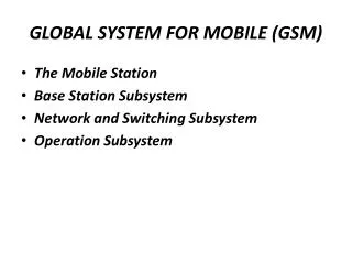
An Overview on the GSM Subsystems • A GSM network comprises several elements: • Mobile station (MS) • Subscriber identity module (SIM) • Base transceiver station (BTS) • Base station controller (BSC) • Transcoding rate and adaptation unit (TRAU) • Mobile services switching center (MSC) • Home location register (HLR) • Visitor location register (VLR), and • Equipment identity register (EIR) • Together, they form a public land mobile network (PLMN)
Um Interface Abis interface A interface
Mobile Station • GSM-PLMN contains as many MSs as possible, available in various styles and power classes
Subscriber Identity Module • Distinction between the identity of the subscriber and mobile equipment • Determines the directory number and the calls billed to a subscriber • A database on the user side • Physically, a chip, inserted into the GSM telephone before use • Format of a credit card or a plug-in SIM • Communicates directly with the VLR and indirectly with the HLR
Base Transceiver Station & Base Station Controller • A large number of BTSs perform radio-related tasks and provide the connectivity between the network and the mobile station via the Air-interface • The BTSs of an area are connected to the BSC via Abis interface. The BSC takes care of all the central functions and the control of base station subsystem (BSS). The BSS comprises the BSC itself and the connected BTSs
Transcoding Rate and Adaptation Unit • An important aspects of a mobile network • Compresses data over Air- interface to use the allocated bandwidth effectively • Data compression is performed in both the MS and the TRAU • From the architecture perspective, the TRAU is part of the BSS • Graphical representation of the TRAU is a black box or, more symbolically, a clamp
Mobile Services Switching Center • A large number of BSCs are connected to the MSC via the A-interface • Very similar to a regular digital telephone exchange and is accessed by external networks exactly the same way • Major tasks are the routing of incoming and outgoing calls and the assignment of user channels on the A-interface
Home Location Register • MSC is only one subcenter of a GSM network • Another subcenter is the HLR, a repository that stores the data of a large number of subscribers • Can be regarded as a large database that administers the data of literally hundreds of thousands of subscribers • Every PLMN requires at least one HLR
Visitor Location Register • Devised to prevent overburdening of HLR with inquiries on data about its subscribers • Like the HLR, a VLR contains subscriber data, but only part of the data in the HLR and only while the particular subscriber roams in the area for which the VLR is responsible • When the subscriber moves out of the VLR area, the HLR requests removal of the data related to a subscriber from the VLR • Geographic area of the VLR consists of the total area covered by those BTSs that are related to the MSCs for which the VLR provides its services
Equipment Identity Register • The theft of GSM mobile telephones seems attractive, since the identities of subscribers and their mobile equipment are separate • Stolen equipment can be reused simply by using any valid SIM • Barring of a subscriber by the operator does not bar the mobile equipment • To prevent this, every GSM terminal equipment contains a unique identifier, the international mobile equipment identity (IMEI). • PLMN normally equipped with an additional database, the EIR, in which stolen equipment is registered and so can be used to bar fraudulent calls and even, theoretically, to track down a thief (by analyzing the related SIM data) • IWF (Inter Working Function) • Provides function to enable the GSM /CDMA System to interface with Public/Private Data Networks. • The basic feature of the IWF are • Data Rate Conversion • Protocol adaptation
The Mobile Station and the SubscriberIdentity Module • GSM telephone set and the SIM are the only system elements with which most users of GSM have direct contact • GSM telephone set and the SIM form an almost complete GSM system within themselves with all the functionality, from ciphering to the HLR
Subscriber Identity Module • A microchip that is planted on either a check card (ID-1 SIM) or a plastic piece about 1 cm square (plug-in SIM) • Except for emergency calls, a GSM mobile phone cannot be used without the SIM • The mobile equipment becomes a mobile station when the SIM is inserted
Subscriber Identity Module • SIM as a Database • The major task of a SIM is to store data • Advantage for the Subscriber • Permits separation of GSM telephone equipment and the related database • GSM subscriber identified by SIM instead of mobile equipment which is always inserted into the equipment before it can be used • This is the basis for personal mobility
Mobile Station • A GSM terminal is a technical marvel • All the functionality known from the BTS transmitter/receiver (TRX), like GMSK modulation/demodulation up to channel coding/decoding, also needs to be implemented in an MS • From the perspective of the protocol, the MS is not only a peer of the BTS but communicates directly with the MSC and the VLR, via the mobility management (MM) and call control (CC) • The most common way to distinguish among GSM mobile equipment is by the power class ratings, in which the value specifies the maximum transmission power of an MS
Functionality of Mobile Station The most important and mandatory features are • Short-message service (SMS) capability • Availability of the ciphering algorithms A5 • Display capability for short messages, dialled numbers, and available PLMN • Support of emergency calls, even without the SIM inserted • “Burned-in” IMEI
The Base Station Subsystem • Via the Air-interface, the BSS provides a connection between the MSs of a limited area and the network switching subsystem (NSS). • The BSS consists of the following elements: • One or more BTSs (base tranceiver station); • One BSC (base station controller); • One TRAU (transcoding rate and adaptation unit)
Base Transceiver Station • The BTS provides the physical connection of an MS to the network in form of the Air-interface • On the other side, toward the NSS, the BTS is connected to the BSC via the Abis-interface • Size reduced considerably, basic structure however, not changed • The GSM Recommendations allow for one BTS to host up to 16 TRXs • In the field, the majority of the BTSs host between one and four TRXs
Architecture and Functionality of a Base Transceiver Station • TRX (Transmitter/Receiver Module) • Most important part of a BTS from the perspective of signal processing • Consists of a low-frequency part for digital signal processing and a high-frequency part for GMSK modulation and demodulation • Both parts are connected via a separate or an integrated frequency hopping unit • All other parts of the BTS are more or less associated with the TRXs and perform auxiliary or administrative tasks
Architecture and Functionality of a Base Transceiver Station Operations and Maintenance Module • Consists of a central unit, which administers all other parts of the BTS • Connected directly to the BSC by means of a specifically assigned O&M channel • That allows the O&M module to process the commands from the BSC , MSC or OMC directly into the BTS and to report the results • Typically, the central unit also contains the system and operations software of the TRXs • That allows it to be reloaded when necessary, without the need to “consult” the BSC • O&M module provides a human-machine interface (HMI), which allows for local control of the BTS
Architecture and Functionality of a Base Transceiver Station Clock Module • Module for clock generation and distribution also part of the O&M area • BTS reference clock is driven from the PCM signal on the Abis-interface • However BTS internal clock generation is mandatory and needed when a BTS has to be tested in a standalone environment, that is, without a connection to a BSC or when the PCM clock is not available due to link failure
Architecture and Functionality of a Base Transceiver Station Clock Module • Cost saving benefit in the approach of deriving the clock from the PCM signal • Much cheaper internal clock generators can be applied, as they do not require the same long-term stability as an independent clock generator • Also less frequent maintenance checks on the clock modules, since they synchronize themselves with the clock coming from the PCM link
Architecture and Functionality of a Base Transceiver Station Clock Module • For errors in call handling, particularly in the area of handover, even minor deviations from the clock have to be considered as possible causes for errors • GSM requires that all the TRXs of a BTS use the same clock signal • The accuracy of the signal has to have a precision of at least 0.05 parts per million (ppm) • For example, a clock generator that derives the clock from a 10 MHz signal has to be able to provide a clock with a frequency accuracy of 10 MHz ±0.5 Hz (10 MHz × 0.05 × 10-6 = 0.5 Hz) • Input and Output Filters • Used to limit the bandwidth of the received and the transmitted signals to 200khz
Base Station Controller • The BSC forms the centre of the BSS • Connects to many BTSs over the Abis-interface • From a technical perspective, a small digital exchange with some mobile-specific extensions • Defined with the intention of removing radio-related load from the MSC • Architecture and tasks are a consequence of that goal
Architecture and Tasks of the Base Station Controller Switch Matrix • Switching of incoming traffic channels (A-interface from the MSC) to the correct Abis-interface channels • Comes with a switch matrix that • takes care of the relay functionality and • can be used as the internal control bus Terminal Control Elements of the Abis-Interface • Connection to the BTSs established via the Abis-terminal control elements (TCEs), which independently from the BSC’s central unit, provide the control function for a TRX of a BTS • The number of Abis TCEs that a BSC may contain depends largely on the number of BTSs and on the system manufacturer • Major tasks of the Abis-TCEs are • set up LAPD connections toward the BTS peers for transfer of signaling data, and • transparent transfer of payload
Architecture and Tasks of the Base Station Controller • May also look after the administration of BTS radio resources, which requires assignment and release of signalling and traffic channels • over the Abis-interface and the Air interface • and for the evaluation of measurement results from the BTS concerning busy and idle channels, which are relevant for power control and used in making decisions about handovers. • Connections from the Abis TCEs to the A-TCEs are realized by the switch matrix • On the other side, the PCM connections are achieved by associated transmission elements
Architecture and Tasks of the Base Station Controller A-Interface Terminal Control Elements • Connection of a BSC to the MSC established via the A-TCEs • Every BSC connected to only one MSC • A large number of A-TCEs needed to convey payload and signalling data of the entire BSS • A-TCEs sets up and operates the SS7/SCCP connection toward the MSC • The number of necessary signaling channels depends largely on the predicted traffic load
Database • BSC being the control centre of the BSS maintains a large database which dynamically administers • The maintenance status of the whole BSS • The quality of the radio resources and terrestrial resources • BSC database also contains the complete BTS operations software for all attached BTSs and all BSS specific information, such as assigned frequencies
Central Module • A major task of the BSC is to decide about a handover • It may decide on intra-BTS handover and intra-BSC handover without needing the MSC • For all BSC external handovers, the BSC needs to involve the MSC • Handover decision and power control are main tasks of the central module Connection to the OMC • Connection to the OMC • Every BSS supervised and managed by an OMC via the BSC
Trans-coding Rate and Adaptation Unit Function of the Trans-coding Rate and Adaptation Unit • Typically located between the BSC and the MSC • Compress or decompress speech between the MS and the TRAU • The used method called regular pulse excitation–long term prediction (RPE-LTP) • Compress speech from 64 Kbps to 16 Kbps, in the case of a full rate channel and to 8 Kbps in the case of a half rate channel • TRAU is not used for data connections
Trans-coding Rate and Adaptation Unit Site Selection for Trans coding Rate and Adaptation Unit • Speech compression intended mainly to save resources over the Air-interface • Also suitable to save line costs when applied on terrestrial links • When installed at the MSC site (top), a fullrate speech channel uses only 16 Kbps over the link from the BSC to the MSC • Can be installed between the BTS and the BSC. • This requires the use of 64-Kbps channels between the BSC and the MSC and hence the use of more links (bottom) • This variant is, therefore, used only infrequently • Mostly the TRAU installed at the site of the MSC to get the most benefit from the compression