PMT measurements in Antares
170 likes | 310 Vues
PMT measurements in Antares. Oleg Kalekin on behalf of Antares collaboration VLVnT 2011 Erlangen 14.10.2011. Motivation Reduction of differences between Monte Carlo and real Antares data charge distribution of the background hits 40 K coincidence rate in two adjacent optical modules

PMT measurements in Antares
E N D
Presentation Transcript
PMT measurements in Antares Oleg Kalekin on behalf of Antares collaboration VLVnT 2011 Erlangen 14.10.2011
Motivation Reduction of differences between Monte Carlo and real Antares data charge distribution of the background hits 40K coincidence rate in two adjacent optical modules hit residual time distribution Improvement in the analysis quality Parameters of Antares PMTs and optical modules Late pulses and after pulses Quantum efficiency Angular acceptance New measurements and simulations O.Kalekin, VLVnT11, Erlangen, 14.10.2011
Angular acceptance of optical modules Measurements: INFN, Genova – water tank, atmospheric muons ECAP, Erlangen – scan of surface; water tank, LED APC, Paris – scan of surface Simulations: Geant 4, thin film theory O.Kalekin, VLVnT11, Erlangen, 14.10.2011
Angular acceptance, INFN Genova The experimental apparatus: • 2 plastic scint to detect m track • water tank (130x150 cm) • black absorbing walls • OM support allows rotations • 0<q<90° • 90<q<180° • 0 < f <180° unfortunately the water level is limited.... measurements from q >90° O.Kalekin, VLVnT11, Erlangen, 14.10.2011
Angular acceptance, INFN Genova Measurements: 1st set: First set of measurement done with improved stable conditions 2nd set: A further absorbing tissue was positioned in the tank 3rd set: Measurements performed to check reproducibility O.Kalekin, VLVnT11, Erlangen, 14.10.2011
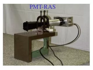
Scans of OMs, ECAP Goniometer like scanner Step motors, steps 1 deg Optical fibre 1mm diameter LED pulses, ~10 ns FWHM A few tens photoelectrons (phe) A few hundred pulses in each measured point Charge recorded with ADC Mean charge – gauss fit OM orientation, top view: Dynode window shown at centre Pins 19 and 20 on the right side Scan numbers shown 1 N 3 4 2 O.Kalekin, VLVnT11, Erlangen, 14.10.2011
Scans of OMs, ECAP O.Kalekin, VLVnT11, Erlangen, 14.10.2011
Angular acceptance, ECAP Water-tank 2x2x3.5 with sweet water LED pulses, ~10 ns FWHM 2.5cm diameter diffuser Distance diffuser – OM geometrical centre 294cm A few tens photoelectrons (phe) A few hundred pulses in each measured point Charge recorded with ADC Mean charge – gauss fit O.Kalekin, VLVnT11, Erlangen, 14.10.2011
Scans of OMs, APC Black box 1m x 1m x 2m Robot – all positions, angles LED inside of diffusive sphere NIST photodiode to control light intensity – absolute calibration Output hole 0.067 μm2 O.Kalekin, VLVnT11, Erlangen, 14.10.2011
Scans of OMs, APC Parallel beam: 756 points 1 cm spacing 106 triggers per point 5 dierent angles: 0, 23, 38, 120 and 138 O.Kalekin, VLVnT11, Erlangen, 14.10.2011
Angular acceptance – simulations Geant4 with thin layer theory implemented PMT angular acceptance tuned to fit measurements (scans) O.Kalekin, VLVnT11, Erlangen, 14.10.2011
Angular acceptance – simulations O.Kalekin, VLVnT11, Erlangen, 14.10.2011
Angular acceptance Simulation vs measurements in water tanks O.Kalekin, VLVnT11, Erlangen, 14.10.2011
Absolute calibration APC: OM Efficiency 15.1% ECAP: OM1018 11.7% - bad glass transparency in the central part OM630 15.5% OM and photodiode illuminated simultaneously with LED pulses OM – diaphragm ~0.75mm diameter, photodiode – full size 1.5x1.5mm OM in a box, 316cm from LED; photodiode – 6cm lower, 13cm closer Measured: OM – charge with ADC, 60ns window, at 1kHz an at 200kHz Photodiode – current at 500kHz and at 2MHz O.Kalekin, VLVnT11, Erlangen, 14.10.2011
Afterpulses INFN, Genova R7081 10inch PMT, active ISEG base Hamamatsu Picosecond Light Pulser PLP10-044C, 440nm wavelength 0.3 photoelectron threshold discriminator CAEN digitizer V1731, 1GHz ~10-2 photons/pulse O.Kalekin, VLVnT11, Erlangen, 14.10.2011
Afterpulses Delayed pulses 28% 2.5% afterpulses 0.8% 0.1% - charge>6pe afterpulses 1.0% O.Kalekin, VLVnT11, Erlangen, 14.10.2011
Summary Successful PMT/OM tests at different Antares groups Better understanding of the detector response Extension and improvement of test benches expected: APC – water tank, ECAP – afterpulsing O.Kalekin, VLVnT11, Erlangen, 14.10.2011