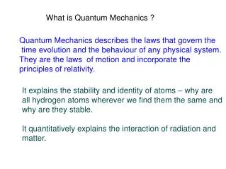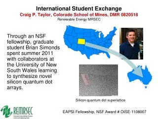
What is a quantum dot?
What is a quantum dot?. Nanocrystals 2-10 nm diameter semiconductors. What is a quantum dot?. Exciton Bohr Radius Discrete electron energy levels Quantum confinement. Motivation. Semiconducting nanocrystals are significant due to;

What is a quantum dot?
E N D
Presentation Transcript
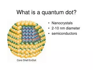
What is a quantum dot? • Nanocrystals • 2-10 nm diameter • semiconductors
What is a quantum dot? • Exciton Bohr Radius • Discrete electron energy levels • Quantum confinement
Motivation • Semiconducting nanocrystals • are significant due to; • strong size dependent optical properties (quantum confinement) • applications solar cells
Terahertz gap 1 THz = 300 µm = 33 cm-1 = 4.1 meV
Time domain terahertz Spectrometer The pulse width = ΔtFWHM/√2 = 17.6±0.5 fs (A Gaussian pulse is assumed)
Terahertz Signal • To obtain the response of the sample to the THz radiation 2 measurements are made • THz electric field transmitted through the empty cell • THz electric field transmitted through the sample cell Fourier Transform
Doping • Intentionally adding impurities to change electrical and optical properties • Add free electrons to conduction band or free holes in valence band • Tin and Indium dopants
Experimental procedure & Data analysis time domain: frequency domain: Power transmittance Relative phase √T(ω), Φ(ω) Complex refractive index (nr(ω) + i.nim(ω)) No Kramer-Kronig analysis!!!
Changes upon charging large quantum dot: Intrinsic Imaginary Dielectric constant • The frequency dependent complex dielectric constants determined • by experimentally obtained • Frequency dependent absorbance and refractive index. The complex dielectric constant = (nr(î) + ini(î))2 • For the charged samples Frohlich Band diminishes: A broader and weaker band appears • The reason of this is the presence of coupled plasmon-phonon modes Nano Lett., Vol. 7, No. 8, 2007
Surface phonon Shift of resonance of tin doped Agreement with charged QDs Results
Semiconductor Quantum Dots Justin Galloway 2-26-07 Department of Materials Science & Engineering
Outline • Introduction • Effective Mass Model • Reaction Techniques • Applications • Conclusion
How • Quantum Dots • Semiconductor nanoparticles that exhibit quantum confinement (typically less than 10 nm in diameter) • Nanoparticle: a microscopic particle of an inorganic material (e.g. CdSe) or organic material (e.g. polymer, virus) with a diameter less than 100 nm More generally, a particle with diameter less than 1000 nm 1.Gaponenko. Optical properties of semiconductor nanocrystals 2.www.dictionary.com
Properties of Quantum Dots Compared to Organic Fluorphores? • High quantum yield; often 20 times brighter • Narrower and more symmetric emission spectra • 100-1000 times more stable to photobleaching • High resistance to photo-/chemical degradation • Tunable wave length range 400-4000 nm Properties CdSe CdTe http://www.sussex.ac.uk/Users/kaf18/QDSpectra.jpg J. Am. Chem. Soc. 2001, 123, 183-184
Excitation in a Semiconductor • The excitation of an electron from the valance band to the conduction band creates an electron hole pair Excitation Creation of an electron hole pair where h is the photon energy Band Gap (energy barrier) exciton: bound electron and hole pair usually associated with an electron trapped in a localized state in the band gap
Recombination of Electron Hole Pairs • Recombination can happen two ways: radiative and non-radiative Release recombination processes radiative recombination photon non-radiative recombination phonon (lattice vibrations)
Effective Mass Model • Developed in 1985 By Louis Brus • Relates the band gap to particle size of a spherical quantum dot Model Band gap of spherical particles The average particle size in suspension can be obtained from the absorption onset using the effective mass model where the band gap E* (in eV) can be approximated by: Egbulk - bulk band gap (eV), h - Plank’s constant (h=6.626x10⁻³⁴ J·s) r - particle radius e - charge on the electron (1.602x10⁻¹⁹ C) me - electron effective mass - relative permittivity mh - hole effective mass 0 - permittivity of free space (8.854 x10⁻¹⁴ F cm-1) m0 - free electron mass (9.110x10⁻³¹ kg) Brus, L. E. J. Phys. Chem. 1986, 90, 2555
Term 2 • The second term on the rhs is consistent with the particle in a box quantum confinement model • Adds the quantum localization energy of effective mass me • High Electron confinement due to small size alters the effective mass of an electron compared to a bulk material Model Consider a particle of mass m confined in a potential well of length L. n = 1, 2, … For a 3D box: n2 = nx2 + ny2 + nz2 Brus, L. E. J. Phys. Chem. 1986, 90, 2555
Term 3 • The Coulombic attraction between electrons and holes lowers the energy • Accounts for the interaction of a positive hole me+ and a negative electron me- Work, w = F·dr Model Electrostatic force (N) between two charges (Coulomb’s Law): Consider an electron (q=e-) and a hole (q=e+) The decrease in energy on bringing a positive charge to distance r from a negative charge is: Brus, L. E. J. Phys. Chem. 1986, 90, 2555
Term Influences • The last term is negligibly small • Term one, as expected, dominates as the radius is decreased Model Modulus Conclusion: Control over the particle’s fluorescence is possible by adjusting the radius of the particle
Quantum Confinement of ZnO & TiO2 • ZnO has small effective masses quantum effects can be observed for relatively large particle sizes • Confinement effects are observed for particle sizes <~8 nm • TiO2 has large effective masses quantum effects are nearly unobservable Model
Formation of Nanoparticles • Varying methods for the synthesis of nanoparticles • Synthesis technique is a function of the material, desired size, quantity and quality of dispersion The Making • Synthesis Techniques • • Vapor phase (molecular beams, flame synthesis etc… • • Solution phase synthesis • Aqueous Solution • Nonaqueous Solution Semiconductor Nanoparticles II-VI: CdS, CdSe, PbS, ZnS III-V: InP, InAs MO: TiO2, ZnO, Fe2O3, PbO, Y2O3 Semiconductor Nanoparticles Synthesis: Typically occurs by the rapid reduction of organmetallic precusors in hot organics with surfactants some examples of in vitro imaging with QDs (http://www.evidenttech.com/)
Nucleation and Growth The Making Figure 1. (A) Cartoon depicting the stages of nucleation and growth for the preparation of monodisperse NCs in the framework of the La Mer model. As NCs grow with time, a size series of NCs may be isolated by periodically removing aliquots from the reaction vessel. (B) Representation of the simple synthetic apparatus employed in the preparation of monodisperse NC samples. Horizontal dashed lines represent the critical concentration for nucleation and the saturation concentration C. B. Murray, C. R. Kagan, and M. G. Bawendi, Annu. Rev. Mater. Sci. 30, 545, 2000.
Capping Quantum Dots • Due to the extremely high surface area of a nanoparticle there is a high quantity of “dangling bonds” • Adding a capping agent consisting of a higher band gap energy semiconductor (or smaller) can eliminate dangling bonds and drastically increase Quantum Yield The Making With the addition of CdS/ZnS the Quantum Yield can be increased from ~5% to 55% Synthesis typically consisted of lower concentrated of precursors injected at lower temperatures at slow speeds Shinae, J. Nanotechnology.2006, 17, 3892
Quantum Dot Images • Quantum dot images prepared in the Searson Lab using CdO and TOPSe with a rapid injection 455000x The Making 770000x 560000x
Quantum Dot Ligands Provide new Insight into erbB/HER receptor – Mediated Signal Transduction • Used biotinylated EGF bound to commercial quantum dots • Studied in vitro microscopy the binding of EGF to erbB1 and erbB1 interacts with erbB2 and erbB3 • Conclude that QD-ligands are a vital reagent for in vivo studies of signaling pathways – Discovered a novel retrograde transport mechanism Application QD’s Dynamics of endosomal fusion A431 cell expressing erbB3-mCitrine Nat. Biotechnol. 2004, 22; 198-203
Multiplexed Toxin Analysis Using Four Colors of Quantum Dot Fluororeagents • Demonstrated multiplexed assays for toxins in the same well • Four analyte detection was shown at 1000 and 30 ng/mL for each toxin • At high concentrations all four toxins can be deciphered and at low concentrations 3 of the 4 Application QD’s Fluoresence data for all 4 toxin assays at high concentrations Cartoon of assay Anal. Chem. 2004, 76; 684-688
Quantum Dot Imaging • QDs with antibodies to human prostate-specific membrane antigen indicate murine tumors developed from human prostate cells • 15 nm CdSe/ZnS TOPO/Polymer/PEG/target Application QD’s Gao et al., “In vivo cancer targeting and imaging with semiconductor quantum dots,” Nat. Biotechnol. 22, 969 (2004).
Magnetic Nanoparticles • Nano-sized magnetic particles can be superparamagnetic • Widely Studied – Suggested as early as the 1970’s • Offers control/manipulation in magnetic field Biological Particles • Co has higher magnetization compared to magnetite and maghemite Science 291, 2001; 2115-2117. J. Phys. D: Appl. Phys. 36, 2003; 167-181. • An Attractive Biological Tool
Magnetic Nanoparticles: Inner Ear Targeted Molecule Delivery and Middle Ear Implant • SNP controlled by magnets while transporting a payload • Studies included in vitro and in vivo on rats, guinea pigs and human cadavers • Demonstrated magnetic gradients can enhance drug delivery Application Magnetic Particles Magnetic Particles Perilymphatic fluid from the cochlea of magnet-exposed temporal bone Perilymphatic fluid samples from animals exposed to magnetic forces Audiol Neurotol 2006; 11: 123-133
Co CdSe ZnS Silica Composite with A Novel Structure forActive Sensing in Livingcells Magnetic Quantum Dot ① Cobalt core : active manipulation • diameter : ~10 nm • superparamagnetic NPs • → manipulated or positioned by an external field without aggregation in the absence of an external field What is MQD ? ② CdSe shell : imaging with fluorescence • thickness : 3-5 nm • visible fluorescence (~450 – 700 nm) • ability to tune the band gap • → by controlling the thickness, able to tune the emission wavelength, i.e., emission color ④ Silica shell : bio-compatibility & functionalization with specific targeting group • thickness : ~10 nm • bio-compatible, • & non-toxic to live cell functions • stable in aqueous environment • ability to functionalize its surface • with specific targeting group ③ ZnS shell: electrical passivation • thickness : 1-2 nm • having wider band gap (3.83 eV) than CdSe (1.91 eV) • enhancement of QY • → CdSe (5-10%) CdSe/ZnS (~50%)
Conclusions • The effective mass model give an excellent approximation of the size dependence of electronic properties of a quantum dot • Recent synthesis advances have shown many quantum dot reactions to be robust, cheap, and safe then previously thought • Quantum dots offer wide range electronic properties that make them an attractive tool for biological and medical work • MQD’s improve afford in vivo manipulation expanded the applicability of quantum dots Rap-Up
3d 4s Energy below the Vacuum level (eV) From an Atom to a Solid Photoemission spectra of negative copper clusters versus number of atoms in the cluster. The highest energy peak corres-ponds to the lowest unoccupied energy level of neutral Cu.Typically, there are two regimes:1) For <102 atoms per cluster, the energy levels change rapidly when adding a single atom (e. g. due to spin pairing).2) For >102 atoms per cluster, the energy levels change continuously (e. g. due to the electric charging energy (next slide).
Energy Levels of Cu Clusters vs. Cluster Radius R Solid Atom ΔE=(E-ER)1/R (charged sphere)
The Band Gap of Silicon Nanoclusters GaAs Bulk Silicon 3 nm : Gap begins to change
The Band Gap of Silicon Nanoclusters 3 nm : Gap begins to change
Increase of the Band Gap in Small Nanoclusters by Quantum Confinement Conduction Band Gap k2 k1 Valence Band
Photon Energy vs. Wavelength: h(eV) = 1240/(nm) The Band Gap of CdSe Nanocrystals Size:
Beating the size distribution of quantum dots Quantum dots formed by thin spots in GaAs layers
Termination of nanocrystals Critical for their electronic behavior H-terminated Si nanocrystal: Electrons stay inside, passivation, long lifetime Oxyen atom at the surface: Electrons drawn to the oxygen Fluorine at the surface: Complex behavior From Giulia Galli’s group
e- e- dot electrons Single Electron Transistor A single electron e- tunnels in two steps from source to drain through the dot. The dot replaces the channel of a normal transistor (below).
Designs for Single Electron Transistors Large (≈m) for operation at liquid He temperature Small (10nm) for operation around room temperature Nanoparticle attracted electrostatically to the gap between source and drain electrodes. The gate is underneath.
* * The elements of this Periodic Table are named after team members from NTT and Delft. Quantum Dots as Artificial Atoms in Two Dimensions Filling electron shells in 2D
Magnetic Clusters “Ferric Wheel”