Download
1 / 5
50 likes | 139 Vues
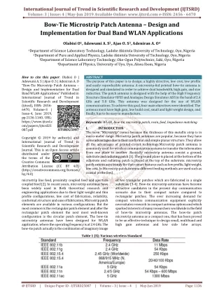
The purpose of this paper is to design a highly directive, low cost, low profile and easily reproducible antenna. A microstrip fed printed bow tie antenna is designed and simulated in order to achieve dual bandwidth, high gain, and size reduction. The patch antenna is designed with the help of the High Frequency Structure Simulator HFSS and Analogue Design Simulator ADS in the band of 2.4 GHz and 5.0 GHz. This antenna was designed for the use of WLAN communications. To achieve this goal, four main objectives were identified. The antenna must have high gain, low build cost, small and light weight design, and finally, has to be easy to manufacture. Olabisi O | Adewumi A. S | Ajao O. S | Adeniran A. O "Bow-Tie Microstrip Patch Antenna Design and Implementation for Dual Band WLAN Applications" Published in International Journal of Trend in Scientific Research and Development (ijtsrd), ISSN: 2456-6470, Volume-3 | Issue-4 , June 2019, URL: https://www.ijtsrd.com/papers/ijtsrd25087.pdf Paper URL: https://www.ijtsrd.com/other-scientific-research-area/other/25087/bow-tie-microstrip-patch-antenna-u2013-design-and-implementation-for-dual-band-wlan-applications/olabisi-o<br>

E N D
International Journal of Trend in Scientific Research and Development (IJTSRD) Volume: 3 | Issue: 4 | May-Jun 2019 Available Online: www.ijtsrd.com e-ISSN: 2456 - 6470 Bow-Tie Microstrip Patch Antenna – Design and Implementation for Dual Band WLAN Applications Olabisi O1, Adewumi A. S2, Ajao O. S3, Adeniran A. O4 1Department of Science Laboratory Technology, Ladoke Akintola University of Technology, Oyo, Nigeria 2Department of Pure and Applied Physics, Ladoke Akintola University of Technology, Oyo, Nigeria 3Department of Science Laboratory Technology, Oke-Ogun Polytechnics, Saki, Oyo, Nigeria 4Department of Physics, University of Uyo, Uyo, Akwa Ibom, Nigeria How to cite this paper: Olabisi O | Adewumi A. S | Ajao O. S | Adeniran A. O "Bow-Tie Microstrip Patch Antenna – Design and Implementation for Dual Band WLAN Applications" Published in International Journal of Trend in Scientific Research and Development (ijtsrd), ISSN: 2456- 6470, Volume-3 | Issue-4, June 2019, pp.1136-1140, URL: https://www.ijtsrd.c om/papers/ijtsrd25 087.pdf Copyright © 2019 by author(s) and International Journal of Trend in Scientific Research and Development Journal. This is an Open Access article distributed under the terms of the Creative Commons Attribution License (CC BY 4.0) (http://creativecommons.org/licenses/ by/4.0) microstrip line feed, proximity coupled feed and aperture coupled feed [2]. In recent years, microstrip antennas have been widely used in Both theoretical research and engineering applications due to their light weight and thin profile configurations, low cost of fabrication, reliability, conformal structure and ease of fabrication. Microstrip patch elements are available in various configurations. But the most common is the rectangular patch element and after the rectangular patch element the next most well-known configuration is the circular patch element. The bow-tie microstrip antennas have been designed for WLAN application, where the operating frequency is at 2.4 GHz. The bow-tie patch actually is the combination of imaginary image ABSTRACT The purpose of this paper is to design; a highly directive, low cost, low profile and easily reproducible antenna. A microstrip-fed printed bow-tie antenna is designed and simulated in order to achieve dual bandwidth, high gain, and size reduction. The patch antenna is designed with the help of the High Frequency Structure Simulator HFSS and Analogue Design Simulator ADS in the band of 2.4 GHz and 5.0 GHz. This antenna was designed for the use of WLAN communications. To achieve this goal, four main objectives were identified. The antenna must have high gain, low build cost, small and light weight design, and finally, has to be easy to manufacture. Keywords: WLAN, Bow-tie, microstrip patch, resin, feed, Impedance matching I. INTRODUCTION The term “Microstrip” comes because the thickness of this metallic strip is in micro-meter range. Microstrip patch antennas are popular, because they have some advantages due to their conformal and simple planar structure. They allow all the advantages of printed-circuit technology.Microstrip patch antenna is commonly used for wireless communication systems to transfer the information from one place to another .Basically microstrip antenna consist a ground, substrate and radiating patch [1]. The ground plane is placed at the bottom of the substrate and radiating patch is placed at the top of the substrate. microstrip patch antenn aare trendy for their smart features such as low profile, light weight, low cost. In Microstrip patch antenna different feeding methods are used such as coaxial probe feed, of two triangular patches which are fabricated in a single substrate [3-4]. Bow-tie microstrip antennas have become attractive candidates in the present day communication scenario due to their compact nature compared to rectangular patches. The ever increasing demand for compact wireless communication equipment explicitly necessitates research in compact antenna options and which sparked interests of many researchers worldwide in the field of bow-tie microstrip antennas. The bow-tie patch microstrip antenna as a compact one, that has been proved to be an effective technique to design small, multiband and high gain antennas and IJTSRD25087 low side lobe arrays. Table 1 [5]: Various wireless Standard @ IJTSRD | Unique Paper ID - IJTSRD25087 | Volume – 3 | Issue – 4 | May-Jun 2019 Page: 1136
International Journal of Trend in Scientific Research and Development (IJTSRD) @ www.ijtsrd.com eISSN: 2456-6470 II. The patch configuration that drives the antenna system to multi-frequency operation is the bowtie shape. Bowtie microstrip antennas are very attractive in present-day communication Systems due to their size, which is smaller than the size of a conventional rectangular patch, although they have similar characteristics and they operate at the same frequency. The shape of a bow-tie microstrip antenna is shown in Fig1. As a substrate material, Resin has been chosen, with dielectric constant of 4.5 because of its properties and cost. The dimensions are 40 x 90 mm2 and the thickness is 2 mm. The conductive material will be used to produce the microstrip arrays elements, the feed network, and the ground plane. Aluminum was considered because of its light weight, non-corrosive, conductivity and energy loss. Design Fig.1 A Typical shape of a bowtie microstrip antenna Z0 = (1) The location of the feed is at the center of the symmetrical microstrip patch design. The antenna is on the above described substrate which has a dielectric constant of 4.5 and the material of the conductor is aluminium. A radiation box was made to enclose the antenna and a perfectly matched layer (PML) material – an artificial absorbing layer is placed around the box. A parameter sweep was used to determine which height should be used to generate a resonant of approximately 2.4GHz. The bowtie printed object comes, substantially, from a rectangular patch via modification and the equations for the approximate calculation of the resonance frequency f in terms of the geometrical and material parameter values [6-7] are: (2) (3) (4) By altering the dimensions Wc and L and keeping W constant it is possible to change the resonance frequency. However for the best impedance matching, the coordinates of the feed point was determined through iterative simulations. The resonant frequency corresponding to the mode TM10 of the equilateral triangular microstrip antenna is [8-9] (5) Where c is the velocity of light in free space, L is the side length of the bow-tie patch and εr is the dielectric constant of the substrate. The above equation is valid when the triangular resonator is enclosed by a perfect magnetic wall. In case it is not valid, the replacement of side length L by an effective value Leff has been suggested [10]. An approximate expression for Leff produced by curve fitting experimental and theoretical results for the resonant frequency for TM10 mode is given by (6) Where h is the thickness of the substrate. @ IJTSRD | Unique Paper ID - IJTSRD25087 | Volume – 3 | Issue – 4 | May-Jun 2019 Page: 1137
International Journal of Trend in Scientific Research and Development (IJTSRD) @ www.ijtsrd.com eISSN: 2456-6470 Fig2. Dimensions of the Antenna Fig3. The Simulated Antenna III. Simulation results for the antenna when works in air Fig.4 and Fig.5 show the radiation Pattern and directivity. Fig. 6 is the Input reflection coefficient, showing that S11= -22dB for f = 2.4GHz and S11= -16 dB for f = 5.0 GHz. Fig.7 show VSWR = 1.1 for f = 2.4 GHz and VSWR = 1.3 for f = 5.0 GHz. The magnitude and angle of the Input Impedance showing that at 2.4 GHz, ZIN = 65 Ω and at 5.0 GHz is 70 Ω approximately. The feeding method used is microstrip feed line is employed. The gain of the antenna was found to be 6.71 dB Results and Discussion Fig4.Radiation Pattern @ IJTSRD | Unique Paper ID - IJTSRD25087 | Volume – 3 | Issue – 4 | May-Jun 2019 Page: 1138
International Journal of Trend in Scientific Research and Development (IJTSRD) @ www.ijtsrd.com eISSN: 2456-6470 Fig5. Directivity Fig6. Input Reflection Coefficient Fig7. VSWR Fig8. Input impedance @ IJTSRD | Unique Paper ID - IJTSRD25087 | Volume – 3 | Issue – 4 | May-Jun 2019 Page: 1139
International Journal of Trend in Scientific Research and Development (IJTSRD) @ www.ijtsrd.com eISSN: 2456-6470 IV. In this paper, dual band Bow-tie microstrip patch antenna has been presented. The design and simulation of the antenna was achieved using HFSS and ADS software. This proposed antenna operates at 2.4 GHz and 5.0 GHz respectively for WLAN applications. The gain of proposed antenna is 6.71 dB with good input reflection coefficient and VSWR. The antenna has shown good performance in terms of directivity and radiation pattern. Acknowledgement The authors sincerely appreciate the contribution of the Electronics Physics Research Group of University of Uyo, Uyo Nigeria for providing software for the simulation and Telecommunication Research and Group of Ladoke Akintola University of Technology, Ogbomoso, Nigeria for the release of GSP-810 Spectrum Analyzer. REFERENCES [1]E. P Ogherohwo,A. O Adeniran , and O. Olabisi “A study of 300, 600, 900 scalene Triangular patch Antenna (TPA) at 900MHZ” International Journal of Research and Reviews in Applied Sciences,www. apparpress . com, 2012,13(2):658-664. Conclusion International Journal of Advanced Research in Electrical Electronics and Instrumentation Engineering, 2013, 2(6): 2727-2735. [4]Hai-Wen Liu, Feng Qin, Jiu-Huai Lei, Pin Wen, Bao-Ping Ren and Xiang Xiao, “Dual-Band Microstrip-Fed Bow- Tie Antenna for Applications”,Microwave and Technology Letters,2014, . 56(9). GPS and Wlan [5]J. Y Zhao, Z. Y Zhang, N. W Wu,G. Fu and S. X Gang, “Wideband Unidirectional Bow-tie Antenna with Pattern Improvement” Progress in Electromagnetic Research Letters, 2010. [6]A. C. Bhosale, V. U. Deshmukh, “Design of Bow-tie Microstrip Antenna with Fractal Shape for WLan Application” International Journal of Electronics & Communication Technology, 2012,3(4):445-449. [7]A. Kaur and Gurpreet B. Kaur and G. Bharti, “U-I Slot Microstrip Patch Antenna for S - Band Applications”, International Journal of Recent Scientific Research, 2016, 7(4):10410-10412. [8]C. A. Balanis, “Antenna Theory, Analysis and Design”, John Wiley & Sons, Inc. U. K. , 2013 [2]T. I Huque. , A. Chowdhury, K. Hosain ,and S. Alam “Performance Analysis of Corporate Feed Rectangular Patch Element and Circular Patch Element 4x2 Microstrip Array Antennas” International Journal of Advanced Computer Science and Applications, 2011,2(7):74-79. [9]T. A. Millikgan, Modern Antenna Design, 2nd ed. , IEEE Press, John Wiley & Sons inc. , 2007. [10]Sagnard, F. and F. Rejiba, “Wide band coplanar waveguide-fed bowtie slot antenna for a large range of ground penetrating radar applications," IETMicrow. Antennas Propag. , 2011 5(6):734-739. [3]M. O Alade and O. Olabisi, “Development of microstrip patch antenna for Terrestrial indoor TV Reception” @ IJTSRD | Unique Paper ID - IJTSRD25087 | Volume – 3 | Issue – 4 | May-Jun 2019 Page: 1140