Download

1 / 4
40 likes | 119 Vues
This paper describes the design and construction of the pedal operated water pump are done especially discharge rate at different speed and height. The proposed pump is a rotary pump operated by pedal power. In the rotary pump, water enters axially through the vane eyes and exits radially. In this paper, necessary dimensions are calculated for the design point of 6.096 m 20 feet height, 0.00018 m3 sec flow rate and rotational speed 260 rpm. Pedal operated water pump is purposed to use in small irrigation and garden irrigation and drinking water where electricity is not available. Ma Myat Win Khaing | Ma Yi Yi Khin | Mg Than Zaw Oo "Design and Construction of Pedal Operated Water Pump" Published in International Journal of Trend in Scientific Research and Development (ijtsrd), ISSN: 2456-6470, Volume-3 | Issue-5 , August 2019, URL: https://www.ijtsrd.com/papers/ijtsrd26434.pdf Paper URL: https://www.ijtsrd.com/engineering/mechanical-engineering/26434/design-and-construction-of-pedal-operated-water-pump/ma-myat-win-khaing<br>

E N D
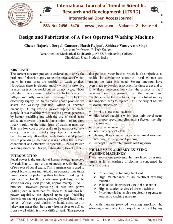
International Journal of Trend in Scientific Research and Development (IJTSRD) Volume 3 Issue 5, August 2019 Available Online: www.ijtsrd.com e-ISSN: 2456 – 6470 Design and Construction of Pedal Operated Water Pump Ma Myat Win Khaing1, Ma Yi Yi Khin2, Mg Than Zaw Oo1 1Lecturer, Department of Mechanical Engineering, Technological University, Taunggyi, Myanmar 2Assistant Lecturer, Department of Mechanical Engineering, Technological University, Mandalay, Myanmar How to cite this paper: Ma Myat Win Khaing | Ma Yi Yi Khin | Mg Than Zaw Oo "Design and Construction of Pedal Operated Water Pump" Published in International Journal of Trend in Scientific Research and Development (ijtsrd), ISSN: 2456- 6470, Volume-3 | Issue-5, August 2019, https://doi.org/10.31142/ijtsrd26434 Copyright © 2019 by author(s) and International Journal of Trend in Scientific Research and Development Journal. This is an Open Access article distributed under the terms of the Creative Commons Attribution License (CC (http://creativecommons.org/licenses/by /4.0) This innovation is useful for pumping water from the river, ponds, wells and similar water sources thus enabling poor farmers for pumping water for irrigation and cultivation. 2.Operation of a Rotary Pump Pump is a device, which raises or transfers liquids at the expense of power input. It is a machine and designed to elevate, deliver and move various liquids or a device that transfers the mechanical energy into potential and kinematic energy of a liquid. Rotary pumps are positive displacement pumps that utilize rotary, rather than reciprocating, motion in their pumping action. They can be designed to pump liquids, gases, or mixtures of the two. As is the case with reciprocating pumps, their capacity per rotation is independent of driven speed. Unlike reciprocals, however, they develop a dynamic liquid seal and do not require inlet and discharge check valves. Since the rotating element of the pump directly connected to its driver via a shaft, some sort of drive shaft sealing arrangement is required. This is usually accomplished a stuffing box, lip seal, or a mechanical seal. ABSTRACT This paper describes the design and construction of the pedal-operated water pump are done especially discharge rate at different speed and height. The proposed pump is a rotary pump operated by pedal power. In the rotary pump, water enters axially through the vane eyes and exits radially. In this paper, necessary dimensions are calculated for the design point of 6.096 m (20 feet) height, 0.00018 m3/sec flow rate and rotational speed 260 rpm. Pedal- operated water pump is purposed to use in small irrigation and garden irrigation and drinking water where electricity is not available. KEYWORDS: Flow rate, Rotary, Pump, Pedal, Speed 1.INTRODUCTION Pedal-operated water pump is a pump operated by pedal power. Pedal operated water pump works on mechanical energy without electricity. It is used to lift water in city when there no electricity or load shedding and also in a remote area where there is no electricity. When the pedal is done, bicycle wheel rotates, so finally it rotates a rotary pump which lifts water. In a pedal operated water pump, a rotary water pump which is run by rotating the pedal of a cycle. The system comprises a bicycle, rim, vane, pulley and inlet and delivery pipes. A wheel is connected to another pulley with a smaller diameter the final supporting shaft is connected with a rotor through this process of paddling is used to lift water from a pipe into the form for cultivation. IJTSRD26434 pp.640-643, BY 4.0) 3.Specification The hand-rotary pump is for transferring oil, water, alcohol, diesel, fuel, gasoline, alcohol, toluene and solvents. High volume delivery at low pressure makes pumping. Each part of the rotary pump shows in Figure 2 and Table I. Figure 2.Parts of a Rotary Pump Table I. Materials of Rotary Pump Component Position Denomination 1 Casing 2 Rotor 3 Vanes 4 Spring 5a Shaft O-Ring 5b Casing/ Cover O-Ring 6 Cover-Casting Screw 7 Handle 8 Washer 9 Nut 10 Cotter 11 Cover Materials Cast iron Bronze Host form INOX Teflon Teflon Steel Galvanized steel Steel Steel Steel Cast iron Figure 1.Rotary Pump @ IJTSRD | Unique Paper ID – IJTSRD26434 | Volume – 3 | Issue – 5 | July - August 2019 Page 640
International Journal of Trend in Scientific Research and Development (IJTSRD) @ www.ijtsrd.com eISSN: 2456-6470 4.Process of Fabrication The first step of making power operated water pump is the preparation of the stand. Scarp mild steel pipes are made into sufficient pieces and are welded together to get the stand. The stand is then connected with the back wheel of the bicycle. By considering the wheel and rotor shaft space the regenerative turbine pump is connected with the stand by using the nut and bolts. The suction and delivery pipes are then connected to the suction and delivery ports respectively. Manual priming of the centrifugal pump is done next. By pedaling the rpm of the rotor shaft is measured using tachometer. The flow rate of water is measured by using the measuring tank and stopwatch. Where, C m/L = Total mass of the chain per length (kg/m) v = Speed of the chain (m/s) Length of Chain, The length of the chain is the product of the number of chain links and the pitch. L = K. px Where, L= Length of chain (mm) K = Chain link Px = Sprocket of pitch (mm) Number of chain links, x P 2 Where, x = Center distance between chain sprocket (mm) T1= Numbers of teeth on big sprocket T2 = Numbers of teeth on small sprocket Tension in Chain due to Sagging, x mg k x W k S Where, m = mass of the chain in kg per meter length x = center distance in meters k = constant which takes into account the arrangement of the chain drive = 2 to 6, when the centerline of the chain in inclined to the horizontal at an angle less than = 1 to 1.5, when the centerline of the chain in inclined to the horizontal at an angle greater than x p Power Transmitted, v B P × Where, B V = Velocity of chain (m/s) N = Factor of safety, and K = Service factor Tangential Driving Force, (inwatts) smitted Power tran T = Centrifugal tension (N) F 5 2 + − T 1 T T 1 T x P x 2 2 + + × 6 K = 2 2π x Figure 3.Process of Fabrication 5.Calculation 5.1 Pedal Operated Water Pump Calculation Formula Sprocket, A sprocket or sprocket-wheel is a profiled wheel with teeth, or cogs, that mesh with a chain, track or other perforated or indented material. 1 T 2 Where, T1= Number of teeth on the smaller sprocket or gear T2= Number of teeth on the larger sprocket 1 d =Front sprocket of diameter (mm) d = Rear sprocket of diameter (mm) Chain Design, The chain drive assumes a special position in the large group of drive mediums for the transmission of torque and power. V.R = 1 2 Where, T = Numbers of teeth on big sprocket = ⋅ ⋅ = ⋅ ⋅ F (Newton) 7 180 o 1 = P d sin 40 x 1 o 40 180 P 2 = d sin x 2 = Sprocket of pitch (mm) T x P = Pitch (mm) × W = 8 n K S W = Breaking load in newton’s, 2 S N 1 T 2 P = 3 = = F 9 N T Speed of chain in m/s v Design of Power, Power is the rate at which energy is applied to a system (Watts = Joules/Second). The power transmitted by the chain is given by: Design power = Rated power × Service factor Where, K1 = Load factor, K2 = Lubrication factor and K3 = Rating factor 1 T= Numbers of teeth on small sprocket 2 N = Speed of front sprocket (rpm) 1 10 N = Speed of rear sprocket and wheel (rpm) Centrifugal Tension in the Chain, 2 v m C 2 ⋅ = (Newton) 4 F L @ IJTSRD | Unique Paper ID – IJTSRD26434 | Volume – 3 | Issue – 5 | July - August 2019 Page 641
International Journal of Trend in Scientific Research and Development (IJTSRD) @ www.ijtsrd.com eISSN: 2456-6470 Rated power, 2 P = − d d 3 4 = sinα 18 × × × N T π 11 2C 60 Torque, T = F × R 15 15 15 Where, P = Rate Power (Watt) T = Torque (Nm) F = Force (N) R = Radius (m) Velocity Ratio of a Belt Drive, The velocity ratio of a belt drive may be broadly defined as the ratio of the velocities of the driver and the follower or driven. (3.15) = ± 180 2α θ 19 Where, 1 θ = angle of wrap of pulley θ = angle of wrap of rear rim µ = coefficient of friction between pulley and belt Length of the Belt, Length of the belt means the total length of the belt, required to connect a driver and a follower. ( Where, L = Length of the belt (mm) C = Center distance of pulley and rear wheel bicycle (mm) D = Diameter of rear wheel bicycle (mm) d = Diameter of pulley (mm) Flow Rate, In physics and engineering, in particular fluid dynamics and hydrometric, the volumetric ?low rate (also known as volume ?low rate, rate of ?luid ?low or volume velocity) is the volume of ?luid which passes per unit time; usually represented by the symbol Q (sometimes V?). Q = n vol s Where, Q = Flow rate,mm3/s n = revolution per second ,rev/s V = Swept volume (mm3) η = Volumetric efficiency Output Power, The output power is the power applied to the fluid to meet the requirement of network throughput. H ρgQ P = Where, Q = Fluid flow rate through the pump, m3/s g = Gravitational acceleration (9.81 ms-2) H = Total Differential Height (m) ρ = Density of the fluid beyond pumped (water: 1000 kg/m3) Input power, Input power is always greater than output power due to the friction in the pump. Pump efficiency is the ratio of these two values. Power Output 2 ) ( ) 2 + − d d d d π 3 4 3 4 + L = 2 × C + 20 × 2 4 C Figure4. Chain and Belt Drive Let, The velocity ratio of the sprocket 1 and 2, 2 2 Similarly, the velocity ratio of the pulleys 3 and 4. 4 4 Torque on the shaft because of power transmitted is: 9550 t Torque on the shaft due to belt drive power transmission is: d ) 2 1 t d ) 2 1 rpm d1 = Diameter of front sprocket (mm) d2 = Diameter of rear sprocket (mm) d3 = Diameter of rear-wheel (mm) d4 = Diameter of pulley (mm) N1 = Speed of the front sprocket N2 = Speed of the rear sprocket N3 = Speed of the rear wheel N4 = Speed of the pulley × V × 21 η N 1 T = 12 N T 1 s N d 3 = 13 vol N d 3 = × M kW 14 rpm 22 4 = − M (T T 15 2 9550 4 = × = − M kW (T T 16 t 2 belt tension, µθ T sin β 1 17 = e T P o 2 Pump Efficiency = = 23 Input Power iP @ IJTSRD | Unique Paper ID – IJTSRD26434 | Volume – 3 | Issue – 5 | July - August 2019 Page 642
International Journal of Trend in Scientific Research and Development (IJTSRD) @ www.ijtsrd.com eISSN: 2456-6470 Table II. Rotary Pump at Tested Discharges No. Rotary Pump Shaft n =260 rpm, ( 4.33 rps ) 11 4.33 rps 22 4.33 rps 33 4.33 rps 44 4.33 rps Tested Discharge, Q(m3/s) 11 liter/min or (0.00018 m3/s) 15 liter/min or (0.00025 m3/s) 27 liter/min or (0.00045 m3/s) 40 liter/min or (0.0006 m3/s) Tested Height (m) 6.096 m 4.572 m 3.048 m 1.524 m Table III. Result Data of Pump Efficiency and Power No Pump Efficiency Volumetric Efficiency Output Power (Watt) 11 0.8 0.0219 22 .8 0.0412 33 0.8 0.0108 44 0.8 0.0289 Input power (Watt) 13.45 14.01 16.83 11.21 10.76 11.21 13.46 8.97 Table IIIV. Result Data of RPM and Height of Front Sprocket and Rear Wheel No. Front sprocket, rev/min Rear sprocket & wheel, rev/min Rotary pulley, revv/min 1 50 2 66 3 84 4 88 100 133 168 175 260 346 437 455 Figure5. The graph between Discharge and Height 6.Discussion and Conclusion The pedal pump designed and constructed, so that a long time operation is possible with high efficiency. It is simple and rigid in construction, compact and portable. Manufacturing cost is lesser than the modern water pumping machine. The power saved and good exercise for all people. It uses manual power hence no fuel is required. Operation is economically and less maintenance cost. The operation is not much noisy. 7.REFERENCES [1]M. ZAKARIA HOSSAIN AND M. ABDULKHAIR “Design and Development of Pedal Pump for Low Lift- Irrigation” Publisher JARD (2001). [3]Shafting, Pulleys, Belting, Rope Transmission, and Shaft Governors by Hubert Edwin Collins (Author), Published by General. Books (2001). [4]“A Textbook of Fluid Mechanics” by Rajput. SCHAND & COMPANY LTD (2001). [5]“Engineering Mechanics” (S.I Units) By R. S. Khurmi (2001). [6]ADEMOLO SUMUEL AKINWANMI, STEPHANKWASI ADZIMAH, FREDRICK OPPONG “Pedal Powered Centrifugal Pump Purified Water Supply Device” Published by Innovative System Design and Engineering (2001). [7]“Fluid mechanics and Hydraulic Machine” By DR. R. K. Bansallaxmi publication (p) ltd (2001). [2]“Nonconvectional sources of energy” fourth edition 2008 By G. D. RAI Khanna publisher. [8]“Machine Design” (S. I. Units) By R. S. Khurmi & J. K. Gupta. @ IJTSRD | Unique Paper ID – IJTSRD26434 | Volume – 3 | Issue – 5 | July - August 2019 Page 643