Download
1 / 5
50 likes | 166 Vues
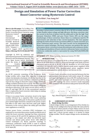
Nowadays various power converters like AC DC or DC DC are widely used due to their flexible output voltage and high efficiency. But these converters take the current in the form of pulses from the utility grid so that the high Total Harmonic Distortion THD and poor Power Factor PF are the major disadvantages of these converters. Hence there is a continuous need for PF improvement and reduction of line current harmonics. The most popular topology for Active Power Factor Correction APFC is a boost converter as it draws continuous input current. This input current can be manipulated by Hysteresis control technique. The boost converter can perform this type of active power factor correction in many discontinuous and continuous modes. The design and simulation of boost converter with power factor correction in continuous conduction mode is represented by using MATLAB SIMULINK software. Yu Yu Khin | Yan Aung Oo "Design and Simulation of Power Factor Correction Boost Converter using Hysteresis Control" Published in International Journal of Trend in Scientific Research and Development (ijtsrd), ISSN: 2456-6470, Volume-3 | Issue-5 , August 2019, URL: https://www.ijtsrd.com/papers/ijtsrd27905.pdf Paper URL: https://www.ijtsrd.com/engineering/electrical-engineering/27905/design-and-simulation-of-power-factor-correction-boost-converter-using-hysteresis-control/yu-yu-khin<br>

E N D
International Journal of Trend in Scientific Research and Development (IJTSRD) Volume 3 Issue 5, August 2019 Available Online: www.ijtsrd.com e-ISSN: 2456 – 6470 Design and Simulation of Power Factor Correction Boost Converter using Hysteresis Control Yu Yu Khin1, Yan Aung Oo2 1Assistant Lecturer, 2Pro-Rector 1,2Mandalay Technological University, Mandalay, Myanmar How to cite this paper: Yu Yu Khin | Yan Aung Oo "Design and Simulation of Power Factor Correction Boost Converter using Hysteresis Control" Published in International Journal of Trend in Scientific Research and Development (ijtsrd), ISSN: 2456- 6470, Volume-3 | Issue-5, August 2019, pp.2312-2316, https://doi.org/10.31142/ijtsrd27905 Copyright © 2019 by author(s) and International Journal of Trend in Scientific Research and Development Journal. This is an Open Access article distributed under the terms of the Creative Commons Attribution License (CC (http://creativecommons.org/licenses/by /4.0) An AC-DC converter consisting of line frequency diode bridge rectifier with a large filter capacitor is cheap and robust, but demands a harmonic rich AC line current. So the input power factor is poor [2].These converters rectify the input AC line voltage to obtain DC output voltage, but this DC voltage oscillates between zero to peak. The filter capacitor is used to reduce the ripple present in the output voltage but introduces distortion in the input current which results in poor PF and high THD [3]. So the conventional capacitor filter is replaced by boost converter which helps in making power factor unity [4]. If there is no power factor correction circuit in the input rectifier followed by a capacitive filter draws pulsating currents from the utility grid. So the power quality become poor and the higher harmonic contents in the power creates bad affect to the other users fed from same grid. Higher harmonics in the current affects the utility grid and other users appliances as well [5]. Various power Factor correction (PFC) techniques are employed to overcome these power quality problems out of which the boost converter topology has been extensively used in various AC-DC and DC-DC appliances [6].The boost topology is very simple and allow low-distorted input currents and almost unity power factor with different control techniques [7]. Boost converter topology in continuous conduction mode (CCM) is used in medium power AC-DC converter, as it gives near unity power factor at AC input [8]. ABSTRACT Nowadays various power converters like AC-DC or DC-DC are widely used due to their flexible output voltage and high efficiency. But these converters take the current in the form of pulses from the utility grid so that the high Total Harmonic Distortion (THD) and poor Power Factor (PF) are the major disadvantages of these converters. Hence there is a continuous need for PF improvement and reduction of line current harmonics. The most popular topology for Active Power Factor Correction (APFC) is a boost converter as it draws continuous input current. This input current can be manipulated by Hysteresis control technique. The boost converter can perform this type of active power factor correction in many discontinuous and continuous modes. The design and simulation of boost converter with power factor correction in continuous conduction mode is represented by using MATLAB/SIMULINK software. KEYWORDS: APFC, Boost Converter, Hysteresis Control, PF, THD I. INTRODUCTION Most electronic devices are supplied by 50 Hz or 60 Hz utility power supplies. Almost in all of the devices power is processed through some kinds of power converters such as AC-DC or DC-DC or DC-AC. Rectifiers i.e. AC to DC power converters are typically used in SMPSs (switch-mode power supplies), ASDs (adjustable-speed drives), UPSs (uninterrupted power supplies), power provisions for communication system devices, test devices etc [1]. IJTSRD27905 BY 4.0) A power factor correction circuit inserted between the line and nonlinear load can give both stable output DC voltage and input side high power factor [9]. PFC methods based on passive and active topologies are discussed and by using active PFC topology the source current is made sinusoidal with minimum THD and almost unity power factor (PF) [10]. Fig.1, Block Diagram of Conventional AC-DC Boost Converter II. A.Diode Bridge Rectifier A diode bridge rectifier is an arrangement of four diodes in a bridge circuit configuration that provides the same polarity of output for either polarity of input. When used in its most common application, for conversion of alternating-current input into a direct-current output, it is known as diode bridge rectifier. The DC output voltage can be calculated by (1) 2V V V 2 V COMPONENTS OF SYSTEM max (1) dc π (2) max rms @ IJTSRD | Unique Paper ID – IJTSRD27905 | Volume – 3 | Issue – 5 | July - August 2019 Page 2312
International Journal of Trend in Scientific Research and Development (IJTSRD) International Journal of Trend in Scientific Research and Development (IJTSRD) @ www.ijtsrd.com www.ijtsrd.com eISSN: 2456-6470 Where, Vmax=maximum peak value Vrms=root means square of voltage Vrms=root means square of voltage Fig. 4, Mode (1) Operation of DC Fig. 4, Mode (1) Operation of DC-DC Boost Converter When the switch is ON, di L L V in dt (5) Fig. 2, Circuit diagram of the diode bridge rectifier Fig. 2, Circuit diagram of the diode bridge rectifier B.Smoothing Capacitor A smoothing capacitor is used in conjunction with a rectifier circuit. It acts to smooth or even out fluctuations in a signal. It is placed across the output of the rectifier and in parallel with the load. Usually when choosing the smoothing capacitor, it is used from anywhere from 10µF to a few thousand µF. The greater the amplitude of the fluctuations and greater the waveform, the larger capacitor will be necessary. V C Assuming, Vr(pp) = 5%of output voltage (peak to peak ripple voltage, V) f = line frequency (50 Hz) R = load resistance (Ω) A smoothing capacitor is used in conjunction with a rectifier acts to smooth or even out fluctuations in a signal. It is placed across the output of the rectifier and in parallel with the load. Usually when choosing the smoothing capacitor, it is used from anywhere from 10µF to a few itude of the fluctuations and greater the waveform, the larger capacitor will be Fig. 5, Mode (2) Operation of DC Fig. 5, Mode (2) Operation of DC-DC Boost Converter max When the switch is OFF, di L f 2fRV (3) r(pp) L V V in out dt (6) During mode (1) operation, energy is stored in the inductor. Load is supplied by capacitor current. During mode (2) operation, energy stored in the inductor is transferred to the load together with the input voltage. Energy is charged in the capacitor. The design calculation of the boost converter can be calculated by the following eq rectified line voltage Vin can be calculated by V 2 V Maximum and minimum value of DC voltage Transfer function is given by (8) V M Maximum and minimum load resistance is given relation V R Maximum and minimum value of duty cycle can be calculated from equation η 1 D Assuming the switching frequency, fs =100 kHz and minimum inductance value can be calculated by 2 min min lmax min 2f And also minimum capacitance value is obtained by V D C During mode (1) operation, energy is stored in the inductor. capacitor current. During mode (2) operation, energy stored in the inductor is transferred to the load together with the input voltage. Energy is charged in the The design calculation of the boost converter can be calculated by the following equations. The single-phase rectified line voltage Vin can be calculated by (7) in rms Maximum and minimum value of DC voltage Transfer out VDC(max, min) Fig. 3, Resultant output waveform with and without smoothing capacitor C.DC-DC Boost Converter Power of the boost converter can come from any suitable DC sources, such as DC generators, batteries, solar panels and rectifiers. The method that changes one DC different DC voltage is called DC to DC conversion. Generally, a boost converter is a DC to DC converter with an output voltage greater than the source voltage. It is sometimes called a step-up converter since it “step voltage. It is a class of switched-mode power supply (SMPS) consists of a power MOSFET, a diode, inductor and capacitor. This converter has the filter inductor on the input side, which provides a smooth continuous input current waveform. Capacitor is normally added to the output of the boost converter to reduce the output voltage ripple. 1 V Here, D is the duty cycle. Vin is the rectified input voltage and Vout is the output voltage. Fig. 3, Resultant output waveform with and without in(min, V (8) max) Maximum and minimum load resistance is given by the Power of the boost converter can come from any suitable DC sources, such as DC generators, batteries, solar panels and rectifiers. The method that changes one DC voltage to a different DC voltage is called DC to DC conversion. Generally, a boost converter is a DC to DC converter with an output voltage greater than the source voltage. It is sometimes up converter since it “step-up” the source out L(max, min) I (9) o(min, max) Maximum and minimum value of duty cycle can be (max, min) mode power supply (SMPS) M (10) VDC(max, min) consists of a power MOSFET, a diode, inductor and capacitor. This converter has the filter inductor on the input side, which provides a smooth continuous input current Assuming the switching frequency, fs =100 kHz and minimum inductance value can be calculated by to the output of the R D (1 D ) boost converter to reduce the output voltage ripple. L (11) s (4) V out in 1 D And also minimum capacitance value is obtained by max R out Here, D is the duty cycle. Vin is the rectified input voltage min f V s lmin cpp (12) @ IJTSRD | Unique Paper ID – IJTSRD27905 27905 | Volume – 3 | Issue – 5 | July - August 2019 August 2019 Page 2313
International Journal of Trend in Scientific Research and Development (IJTSRD) @ www.ijtsrd.com eISSN: 2456-6470 III. CONTROL SCHEME OF POWER FACTOR CORRECTION BOOST CONVERTER When a converter has less than unity power factor, it means that the converter absorbs apparent power higher than active power. So the harmonic currents are generated by the converter. Higher harmonics in the current affects the utility grid and other appliances as well. So the power factor correction is needed. A.Active Power Factor Correction An active power factor correction approach is the most effective way to correct power factor of electronic supplies. The active PFC techniques can be classified as: (1) PWM PFC techniques, (2) Resonant PFC techniques, (3) Soft switching PFC techniques and so on. In PWM PFC approach, the power switching device operates at pulse-width modulation mode. Switching frequency of active power switch is constant, but turned-on and turned-off mode is variable. Here a boost converter is placed between the bridge rectifier and the load. The converter tries to maintain a constant DC output bus voltage and draws a current that is in phase with and at the same frequency as the line voltage. Advantages of boost APFC are as follows: Active wave shaping of input current Filtering of the high frequency switching Feedback sensing of the source current for waveform control Feedback control to regulate output voltage There are various types of control techniques present for improvement of power factor with tight output voltage regulation. They are: Peak current control Average current control method Borderline control method Discontinuous current PWM control method Hysteresis control method There are different current mode control techniques to manipulate continuous input current obtained from the boost converter. Among them, Hysteresis Control Method is used because of many advantages over other methods. Hysteresis control method has the constant on-time and the constant off-time control, in which only one current command is used to limit either the minimum input current or the maximum input current. Hysteresis comparators are used to impose hysteresis band around the reference current. The hysteresis control scheme provides excellent dynamic performance because it acts quickly. Also, an inherent peak current limiting capability is provided. This type of control in which two sinusoidal current references IP,ref, IV,ref are generated, one for the peak and the other for the valley of the inductor current. According to this control method, the switch is turned on when the inductor current goes below the lower reference IV,ref and is turned off when the inductor current goes above the upper reference IP,ref, giving rise to a variable frequency control. The block diagram of the hysteresis controller is shown in Figure 6. Advantages: no need of compensation ramp low distorted input current waveforms Disadvantages: variable switching frequency inductor current must be sensed control sensitive to commutation noises Fig. 6, Hysteresis control scheme DESIGN AND MODELLING FOR PFC BOOST CONVERTER In this paper, design calculation and modelling is executed for conversion of 230 V single phase AC input voltage to 400 V DC at 3.4 kW output power. For this conversion, Hysteresis Controlled Mode based PFC boost converter is used. The specifications for the system are as follow: AC input Voltage = 230 V DC output voltage = 400 V Converter Rated Power = 3.4 kW By using equations described in section II, the calculated results for PFC boost converter are shown in TABLE I. TABLE I. THE CALCULATED RESULTS OF SYSTEM DESIGN PARAMETERS Parameters Maximum and minimum value of single-phase rectified line voltage Maximum and minimum value of DC voltage transfer function Maximum and minimum duty cycle Maximum and minimum load resistance Minimum inductance Minimum capacitance Smoothing capacitor For the modelling of MATLAB/SIMULINK software is applied. The model mainly consists of DC-DC boost converter and PFC control circuit. The Simulink models for designed system without PFC control and with PFC control methods are shown in figure 7 and figure 8. IV. Symbols Vin max Vin min M VDC max M VDC min D max D min R l max R l min L min C min C f Ratings 325.27V 261.63V 1.53 1.23 0.419 0.268 941.18 Ω 47.06 Ω 0.692 mH 17 µF 180 µF PFC boosted converter, @ IJTSRD | Unique Paper ID – IJTSRD27905 | Volume – 3 | Issue – 5 | July - August 2019 Page 2314
International Journal of Trend in Scientific Research and Development (IJTSRD) @ www.ijtsrd.com eISSN: 2456-6470 Fig. 7, DC-DC boost converter without PFC control method Fig. 11, Input supply current waveform and FFT analysis without PFC boost converter Fig. 12, DC Output Voltage of boost converter with hysteresis control Fig. 8, DC-DC boost converter with Hysteresis Control based PFC Control Method V. SIMULATION RESULTS FOR PFC BOOST CONVERTER WITH HYSTEERESIS CONTROL METHOD To evaluate the performance of hysteresis control method based PFC boost converter, the simulations are carried out for DC-DC converter without PFC control and with PFC control method. In both case, simulation time is set as 0.5 second and sampling time is 1 µsec. The main measurements are carried out for output DC voltage, input current, power factor and total harmonic distortion of input current. The simulation results are shown in following Figures. Fig. 13, Input Voltage and Input current of the rectifier with hysteresis control Fig. 14, PF with hysteresis control Fig. 9, DC Output Voltage of boost converter without control Fig. 10, PF without PFC boost converter Fig. 15, Input supply current waveform and FFT analysis with hysteresis control @ IJTSRD | Unique Paper ID – IJTSRD27905 | Volume – 3 | Issue – 5 | July - August 2019 Page 2315
International Journal of Trend in Scientific Research and Development (IJTSRD) @ www.ijtsrd.com eISSN: 2456-6470 Comparative results of performance parameters for boost converter without and with control method incorporated from below TABLE II. TABLE II COMPARATIVE RESULTS OF PERFORMANCE PARAMETERS OF BOOST CONVERTER WITH VARIOUS METHODS their help and encouragement and also thanks all her friends. REFERENCES [1]Vijaya Vachak, Anula Khare, Amit Shrivatava, “Power factor correction Circuit: Active Filter”, International Journal of Engineering Research and General Science, Volume2, Issue 5,August-September, 2014. Power Factor (PF) Topology THD (%) [2]Antonio P. Martins, Antonio M. Cardoso, “Input Current Distortion and Output Voltage Regulation of the Power Factor Correction Boost Converter with Different Control Techniques”, ICREPQ’12,28th to 30th March, 2012. Boost Converter (without control method) Hysteresis Control 195.69% 0.8326 1.09% 0.9968 VI. Design calculations of rectifier and boost converter and simulation of PFC boost converter with hysteresis control method by using MATLAB/SIMULINK are presented in this paper. Various measurements consisting of THD and PF are executed. The analysis of circuit with and without PFC boost converter topology is shown. Without PFC boost converter topology, there is a phase difference between input voltage and current and moreover THD is very high. With PFC boost topology, the harmonics distortion in the input current can be removed; hence we can achieve the improvement of PF and reduction of THD. The simulation results show that hysteresis control offers power factor very closely to unity and supply current THD is 1.09%. ACKNOWLEDGMENT The author is deeply gratitude to all her teachers from Department of Electrical Power Engineering, Mandalay Technological University, for the development of this paper. Especially, the author would like to thanks her parents for CONCLUSION [3]A. Karaarslan, I. Iskender, “The Analysis of AC-DC Boost PFC Converter Based on Peak and Hysteresis Current Control Techniques”, IJTPE, Volume 3, Issue 7, June 2011. [4]Sukanta Kumar Sahoo, Hitesh R. Jariwala, “A New Power Factor Correction Technique Using PFC Boost Converter”, IEEE, 2012. [5]Brijesha Patel, Jay Patel, Umang Wani, “A New Active Power Factor Correction Controller Using Boost Converter”, IJIRSET, Volume 5, Issue 5, May 2016. [6]Santhosh Kumar R, Shreeshayana R, “Design and Simulation Analysis of Power Factor Correction Using Boost Converter with IC UC3854”, IJIREST, Volume 6, Issue 5, May 2017. [7]L. Rossetto, G. Spiazzi, P. Tenti, "Control Techniques for Power Factor Correction converters". @ IJTSRD | Unique Paper ID – IJTSRD27905 | Volume – 3 | Issue – 5 | July - August 2019 Page 2316