Download
1 / 5
50 likes | 62 Vues
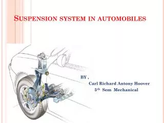
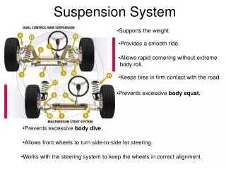
A shock absorber is a mechanical device designed to smooth out or damp a sudden shock impulse and dissipate kinetic energy. Without shock absorbers, the vehicle would have a bouncing ride, as energy is stored in the spring and then released to the vehicle, possibly exceeding the allowed range of suspension movement, Control of excessive suspension movement without shock absorption requires stiffer springs, which would in turn give a harsh ride. Shock absorbers allow the use of soft springs while controlling the rate of suspension movement in response to bumps. Now the project has mainly concentrated in designing a suitable suspension unit. The limit sensor is fixed to the front wheel. When the front wheel is in bounce, the limit sensor activates the pneumatic compressor automatically with the help of electronic control unit. Now the compressor starts running, activating the hydro pneumatic suspensor which is fitted in the back wheel. In a vehicle it reduces the effect of suspension travel on uneven terrains. Hydraulic system undergo torque multiplication in an easy way, independent of distance between input and output. Pneumatic system is based on the fact that gas is compressible so equipment is less subjected to shock loads. M. Boopathi | S. R. Gauthamnithin | S. Harikrishnan | Prof. Dr. G. Kumaresan "Hydro-Pneumatic Suspension with Intelligent Active Suspensioning System" Published in International Journal of Trend in Scientific Research and Development (ijtsrd), ISSN: 2456-6470, Volume-2 | Issue-3 , April 2018, URL: https://www.ijtsrd.com/papers/ijtsrd10916.pdf Paper URL: http://www.ijtsrd.com/engineering/automotive-engineering/10916/hydro-pneumatic-suspension-with-intelligent-active-suspensioning-system/m-boopathi<br>

E N D
International Research Research and Development (IJTSRD) International Open Access Journal Pneumatic Suspension with Intelligent Active Suspensioning System International Journal of Trend in Scientific Scientific (IJTSRD) International Open Access Journal ISSN No: 2456 ISSN No: 2456 - 6470 | www.ijtsrd.com | Volume 6470 | www.ijtsrd.com | Volume - 2 | Issue – 3 Hydro-Pneumatic Active Suspensioning System ith Intelligent Prof. Dr. G. Kumaresan Kumaresan, M. Boopathi, S. R. Gauthamnithin, S. Harikrishnan Department of Mechanical Engineering, Bannari Amman Institute Department of Mechanical Engineering, Bannari Amman Institute Harikrishnan Department of Mechanical Engineering, Bannari Amman Institute of Technology of Technology, Sathyamangalam, Erode, Tamil Nadu, India ABSTRACT A shock absorber is a mechanical device designed to smooth out or damp a sudden shock impulse and dissipate kinetic energy. Without shock absorbers, the vehicle would have a bouncing ride, as energy is stored in the spring and then released to the vehicle, possibly exceeding the allowed range of suspension movement, Control of movement without shock absorption requires stiffer springs, which would in turn give a harsh ride. Shock absorbers allow the use of soft springs while controlling the rate of suspension movement in response to bumps. Now the project ha concentrated in designing a suitable suspension unit. The limit sensor is fixed to the front wheel. When the front wheel is in bounce, the limit sensor activates the pneumatic compressor automatically with the help of electronic control unit. Now the compressor starts running, activating the hydro pneumatic suspensor which is fitted in the back wheel. In a vehicle it reduces the effect of suspension travel on un terrains. Hydraulic system multiplication in an easy way, independen between input and output. Pneumatic system is based on the fact that gas is compressible so equipment is less subjected to shock loads. the degree of mechanization is increased. Degrees of automation are of two types: e of mechanization is increased. Degrees of A shock absorber is a mechanical device designed to sudden shock impulse and dissipate kinetic energy. Without shock absorbers, the vehicle would have a bouncing ride, as energy is stored in the spring and then released to the vehicle, possibly exceeding the allowed range of suspension (1) Full automation, (2) Semi automation. excessive excessive suspension suspension In semi automation a combination of manual effort and mechanical power is required whereas in full automation human participation is very negligible. automation human participation is very negligible. In semi automation a combination of manual effort and mechanical power is required whereas in full movement without shock absorption requires stiffer springs, which would in turn give a harsh ride. Shock absorbers allow the use of soft springs while controlling the rate of suspension movement in response to bumps. Now the project has mainly concentrated in designing a suitable suspension unit. The limit sensor is fixed to the front wheel. When the front wheel is in bounce, the limit sensor activates the pneumatic compressor automatically with the help of Common Approaches for Shock Absorption Common Approaches for Shock Absorption Hysteresis of structural material, for example the sure) compression of rubber disks, (Act of expanding by lengthening or widening) stretching of rubber bands, (The act of bending something) bending of steel springs, or twisting of Hysteresis of structural material, for example the (Applying pressure) compression of rubber disks, (Act of expanding by lengthening or widening) stretching of rubber bands, (The act of bending something) bending of steel springs, or twisting of torsion bars defined. the compressor starts running, activating the hydro pneumatic suspensor which is fitted in the back wheel. In a vehicle it reduces the effect of suspension travel on uneven Need for Automation Automation can be achieved throug hydraulics, pneumatics, robotics, etc., of these sources, pneumatics form an attractive medium for low cost automation. Automation plays an important role in automobile. Nowadays almost all the automobile vehicle is being atomized in order to product the human being. The automobile vehicle is being atomized for the following reasons: being atomized for the following reasons: Automation can be achieved through computers, hydraulics, pneumatics, robotics, etc., of these sources, pneumatics form an attractive medium for low cost automation. Automation plays an important role in automobile. Nowadays almost all the automobile vehicle is being atomized in order to product the human being. The automobile vehicle is undergo undergo torque torque multiplication in an easy way, independent of distance between input and output. Pneumatic system is based on the fact that gas is compressible so equipment is Keywords: Component, designing, working Component, designing, working I. Introduction (Heading 1) (1) To Achieve High Safety, This is an era of automation where it is broadly defined as replacement of manual effort by mechanical power in all degrees of automation. The operation remains an essential part of the system although with changing demands on physical input as although with changing demands on physical input as This is an era of automation where it is broadly defined as replacement of manual effort by mechanical power in all degrees of automation. The operation remains an essential part of the system (2) To Reduce Man Power, (3) To Increase the Efficiency of the Vehicle, (3) To Increase the Efficiency of the Vehicle, @ IJTSRD | Available Online @ www.ijtsrd.com @ IJTSRD | Available Online @ www.ijtsrd.com | Volume – 2 | Issue – 3 | Mar-Apr 2018 Apr 2018 Page: 436
International Journal of Trend in Scientific Research and Development (IJTSRD) ISSN: 2456-6470 spring and then released to the vehicle, possibly exceeding the allowed movement. Control of movement without shock absorption requires stiffer (higher rate) springs, which would in turn give a harsh ride. Shock absorbers allow the use of soft (lower rate) springs while controlling the rate of suspension movement in response to bumps. (4) To Reduce the Work Load, range excessive of suspension suspension (5) To Reduce the Vehicle Accident, (6) To Reduce the Fatigue of Workers, (7) To High Responsibility, (8) Less Maintenance Cost. II. Earlier Methods (Heading 2) In our project, hydraulically and also pneumatically operated suspensor is used to reduce the effect of traveling over rough ground. This system consists of suspensor, oil tank, solenoid valve air tank, electronic control unit, limit sensor and hydraulic tank. Shock absorbers are an important part of automobile suspensions. The limit sensor is fixed to the front wheel. When the front wheel is jumping, the limit sensor activates the control unit. The control unit signal is given to the solenoid valve and it is activated. At the same time, the motor is started which is coupled with rotary hydraulic pump. The oil is suctioned from the oil tank and compressed oil goes to the solenoid valve. The compressed fluid (oil) goes to the hydraulic suspensor (cylinder) which is fixed in the rear wheel. The compressed oil pusses the hydraulic cylinder piston and move forward. The piston moves forward so that the suspensor action carried out. The solenoid valve is deactivated after 3-5 seconds by control timing unit. The hydraulic cylinder fluid (oil) goes to another solenoid valve. Then the oil returns back to the oil tank, by the time of deactivating the solenoid valve. B. Experimental Investigation of Suspension The suspension system of a vehicle serves to provide a comfortable and a safe ride for the vehicles occupants. A balance must be found for the suspension system between being firm enough to support the vehicle chassis and being soft enough to provide a comfortable ride. In two wheelers this is not that difficult a process because the weight is relatively low, so not as much emphasis needs to be placed on providing support. This process however, becomes increasingly more difficult as the weight of a vehicle increases. This becomes a very large problem when it comes to vehicles such as two wheeler, which can weigh upwards of one ton. This is a tremendous amount of weight for the suspension system to support and at the same time the vehicle needs to provide a very smooth ride for the extremely delicate cargo that it transports. Disadvantages Initial cost is high. High maintenance cost. Light vehicle only applicable and accurate. III. Literature Review (Heading 3) A.Design and Fabrication of Suspension with Intelligent Active Suspensioning System The challenge becomes how to provide more rigid support than that needed in a car while providing a more comfortable ride so as not to be detrimental to the condition of the two wheeler being transported. In the following chapter we analyze suspension and compare it to traditional suspension systems. Selecting a suspension system as a replacement for traditional spring and shock absorber suspensions was not an arbitrary decision. We were given the task of softening the ride and improving the comfort while driving. A shock absorber is a mechanical device designed to smooth out or (a slight wetness) damp a sudden shock impulse and dissipate kinetic energy. Now the project has mainly concentrated a suitable suspension unit has been designed. The limit sensor is fixed to the front wheel. When the front wheel is jumping, the limit sensor activates the automatically by electronic control unit and starts running and activates the suspensor which is fitted in the back wheel. pneumatic compressor IV. Components And Description (Heading 4) In a vehicle, it reduces the effect of traveling over rough ground. Without shock absorbers, the vehicle would have a bouncing ride, as energy is stored in the The bearing press consists of the following components to fulfill the requirements of complete operation of the machine are: @ IJTSRD | Available Online @ www.ijtsrd.com | Volume – 2 | Issue – 3 | Mar-Apr 2018 Page: 437
International Journal of Trend in Scientific Research and Development (IJTSRD) ISSN: 2456-6470 In working of 3/2 single acting solenoid (or) cut off valve, the control valve is used to control the flow direction is called cut off valve or solenoid valve. This solenoid cut off valve is controlled by the emergency push button. The 3/2 Single acting solenoid valve is having one inlet port, one outlet port and one exhaust port. The solenoid valve consists of electromagnetic coil, stem and spring. The air enters to the pneumatic single acting solenoid valve when the push button is in ON position. (1) Hydro Pneumatic Cylinder, (2) Solenoid Valve, (3) Flow Control Valve, (4) PU Connector, Reducer, Hose Collar, (5) Electronic Control Unit, (6) Wheel Brake and Stand Arrangement, (7) Power Supply. B. Flow Control Valve A.Cylinder This valve is used to speed up the piston movement and also it acts as an one – way restriction valve which means that the air can pass through only one way and it can’t return back. By using this valve the time consumption is reduced because of the faster movement of the piston. Double acting cylinder is only capable of performing an operating medium in both direction. Double acting cylinders equipped with two inlet for the operating air and hydraulic pressure, can be production in several fundamentally different designs. A double-acting cylinder is used where an external force is not available to retract the piston or where high force is required in both directions of travel. Double cylinders develop power in both direction only. Therefore no heavy control equipment should be attached to them, which requires to be moved on the piston return stoke single action cylinder requires only about half the air volume consumed by a double acting for one operating cycle. C.PU Connectors, Reducer, Hose collar In our system there are two types of connectors used; one is the hose connector and the other is the reducer. Hose connectors normally comprise an adapter (connector) hose nipple and cap nut. These types of connectors are made up of brass or Aluminium or hardened steel. Reducers are used to provide inter connection between two pipes or hoses of different sizes. They may be fitted straight, tee, “V” or other configurations. These reducers are made up of gunmetal or other materials like hardened steel. Solenoid Valve The directional valve is one of the important parts of a system. Commonly known as DCV, this valve is used to control the direction of air flow in the system. The directional valve does this by changing the position of its internal movable parts. D.Electronic Control Unit The control unit is used to suspension the back wheel for the particular time period when there is any input signal from the front wheel. The control unit having one variable resister is there, you have to vary the off time of the timer unit. The OP-AMP 324 IC is used as a comparator. The comparator is giving the output voltages depends upon the two input voltage values. In our project one input voltage (Reference Voltages) is given to the PIN number 2 (negative pin) of 324 IC from the variable resistor (10 K Ohm). The Variable resistance output is given to the OP-AMP pin number 3 (positive pin). This valve was selected for speedy operation and to reduce the manual effort and also for the modification of the machine into automatic machine by means of using a solenoid valve. A solenoid is an electrical device that converts electrical energy into straight line motion and force. These are also used to operate a mechanical operation which in turn operates the valve mechanism. Solenoids may be push type or pull type. The push type solenoid is one in which the plunger is pushed when the solenoid is energized electrically. The pull type solenoid is one is which the plunger is pulled when the solenoid is energized. The name of the parts of the solenoid should be learned so that they can be recognized when called upon to make repairs, to do service work or to install them. In normal condition the voltages applied to the non-inverting terminal (+ive) is low when compared to the inverting terminal voltages (- ive). In that time, the OP-AMP output is –Vsat. (I.e -12 Volt). The transistor and relay are in @ IJTSRD | Available Online @ www.ijtsrd.com | Volume – 2 | Issue – 3 | Mar-Apr 2018 Page: 438
International Journal of Trend in Scientific Research and Development (IJTSRD) ISSN: 2456-6470 “OFF” condition. In that condition, the solenoid valve is off condition. warnings of when it is time to replace them. The first part to let you know that something is wrong is the brake pads. These parts sit on the top of the brake discs, which are large circular metal discs that sit behind the tire in the tire well. When you step on the brakes, the pads squeeze against the discs and stop the car. When the brakes are going bad, the first warning is that you will notice that it is taking longer to stop your car and you have to depress the brake pedal harder than normal. Continuing to drive on worn pads will produce a shuddering and squealing from the brakes, which is telling you that the pads are worn down and metal is grinding against metal. At this point, the discs are susceptible to cracks and could break. In Abnormal condition the voltages applied to the non-inverting terminal (+ ive) is high when compared to the inverting terminal voltages (- ive). In that time, the OP-AMP output is +Vsat. (I.e +12 Volt). The transistor and relay are in “ON” condition. In that time, the solenoid valve is in ON condition for the particular time period, the back wheel suspension occurs. A comparator is a device which is used to sense when a varying signal reaches some threshold value and this comparator output is used to driven logic circuit. The OPAMP is used to construct comparator. It is basically an open-loop op-amp with output ±Vsat (= Vcc) in the ideal transfer characteristics. However, a commercial op-amp has the transfer characteristics. There are basically two types of comparators: F. Power Supply A 12 Volt, V direct current is required to make function of the solenoid valve, which operates only in current. Since all electronic circuits work only with low D.C. voltage we need a power supply unit to provide the appropriate voltage supply. This unit consists of transformer, rectifier, filter and regulator. A.C. voltage typically 230Volt rms is connected to a transformer which steps that AC voltage down to the level to the desired AC voltage. A diode rectifier then provides a full- wave rectified voltage that is initially filtered by a simple capacitor filter to produce a DC voltage. This resulting DC voltage usually has some ripple or AC voltage variations. A regulator circuit can use this DC input to provide DC voltage that not only has much less ripple voltage but also remains the same DC value even the DC voltage varies some what, or the load connected to the output DC voltages changes. In our project we are using step down transformer for providing a necessary supply for the electronic circuits. In our project we are using a 0-12 transformer. (1) Non-inverting comparator, (2) Inverting comparator. The IC324 is an operational amplifier. An operational amplifier is a direct coupled high gain negative feedback amplifier. The op-amp can amplify signals having frequency ranging from 0Hz to 1MHz. It is used to perform a wide verity of linear integrated circuit. There are two inputs. The signal given to the inverting input is always inverted at the output. The signal given to the non inverting input is available at the output without any change in sign. Characteristics of an ideal OP-AMP are: (1) input resistance = infinity, (2) output resistance (R0) = 0, (3) voltage gain, AV = infinity, (4) BandWidth, B.W = infinity, (5) its characteristic does not drift with temperature, and (6) it will be operated up to 1MHz. In filters,the out voltage is essentially constant. We filter the pulsating voltage by using RC filter. The capacitor is made sufficiently large to present very low impedance to the ripple frequency and infinite impedance to DC prefers. The shunt path through C and the steady current (IDC) is forced through R developing a DC voltage drop across it. The ripples are reduced by R&C. E. Wheel Break and Stand Arrangement Wheel suspension systems there is at least one more tremendously important objective: the time history of the vertical wheel forces on the road should be as smooth as possible in order to ensure that a high level of lateral and longitudinal wheel force can be transferred to the road surface at any time. This is one of the systems that greatly benefit from regular inspections because your brakes give you clear @ IJTSRD | Available Online @ www.ijtsrd.com | Volume – 2 | Issue – 3 | Mar-Apr 2018 Page: 439
International Journal of Trend in Scientific Research and Development (IJTSRD) ISSN: 2456-6470 In voltage regulator (IC 78xx Series), The series 78 regulators provide fixed regulated from 5 to 24V. An unregulated input voltage Vi is filtered by capacitor C1 and connected to the IC’s IN terminal. The IC’s OUT terminal provides a regulated +12V which is filtered by capacitor C2. The third IC terminal is connected to ground. While the input voltage may very over some permissible voltage range, and the output load may vary over some acceptable range, the output voltage remains constant within specified voltage variation limits. The 7812 IC then provides an output is a regulated +12V DC. simulates the situation of riding on air, because pockets of gas take the place of mechanical springs. Since suspension has gone through several proofs of concept including real world production applications, we decided to create a kit to modify our F350 to incorporate this type of suspension system. Most important of the proof of concepts, is in its application of high speed military tanks and agricultural tractors which both compare and exceed the weight of our two wheelers. References 1.Carbonaro, O: Hydractive suspension electronic control system. Control philosophy, Konferenz-Einzelbericht: FISITA Congress, Torino, Italy, Vol. 1, pp. 779– 783, May 1990. (references) technology and 23rd V. Working Of Suspension Unlike typical suspension systems, hydro-pneumatic suspension does not have springs. The springs were replaced with only fluid and gas filled interconnected shock absorbers similar to the one seen below. This system was created around the concept that you can compress a gas, but cannot compress a liquid. In this suspension system, the gas (typically nitrogen) acts as a spring, and the hydraulic fluid acts as a damping and leveling mechanism. The system relies on an engine powered hydraulic pump which pressurizes the hydraulics of the system and enables various capabilities including self-leveling, variable ride height, assisted jacking forces, and near zero body roll through hard cornering acceleration. This system also has the capability to power the steering and braking systems to reduce the number of individual components, if desired. 17 Overall, the hydro-pneumatic suspension system provides qualities that can be considered, ideal conditions. These ideal conditions are a constantly level passenger compartment, limited road surface irregularity oscillations, no abrupt vertical motions. 2.Els, hydropneumatic spring and damper system. journal of terramechanics/the international society for terrain vehicle systems, Durham, NC, 35(2), 109–117, 1998. P.S.; Giliomee, C.L.: Semi-active 3.Cao, Dongpu, Subhash Rakheja and Chun-Yi Su. "Optimal damping design of heavy vehicle with interconnected suspension." SAE Technical Paper Series (2007). and hard braking/ 4.Deprez, K, K. Maetens and H. Ramon. "Comfort improvement by passive hydropneumatic suspension optimization technique." Conference. Anchorage, AK: Laboratory for Agro-Machinery and Processing, 2002. 1497- 1501. semi-active using American and global Control 5.Moreau, Xavier, et al. "Improvement hydractive suspension hard mode comfort thanks to a low frequency active crone system." ASME 2009 International Design Engineering [12] Technical Conferences Information in Engineering Conference. San Diego, CA: American Society of Mechanical Engineers, 2009. 1-10. of VI. Conclusion Using a Ford F350 donated by Autotronics, we analyzed all of the possible areas for improvement to accomplish this task. After eliminating vehicle weight, we landed on the reconstruction of the two wheelers suspension system. This current system takes vibrations from the road, and transmits them into the two wheelers, and therefore the passenger compartment. These transferred road vibrations have been proven to cause or worsen drivers. After analyzing several suspension systems, we decided to expand our research on suspension. This suspension system, as explained on previous pages, literally & Computers and 6.Seo, Jeong-Uk, Young-Won Yun and Myeong- Kwan Park. "Magneto-rheological accumulator for temperature compensation in hydropneumatic suspension systems." Journal of mechanical science and technology (2011): 1621-1625. @ IJTSRD | Available Online @ www.ijtsrd.com | Volume – 2 | Issue – 3 | Mar-Apr 2018 Page: 440