Download
1 / 5
50 likes | 68 Vues
Today the application of PLC is more widely used in the digital world. There are many applications of PLC especially in the industrial. Normally, the PLCs that have been used at the industrial field are usually to control the machine or heavy machine in order to create an efficient production process. In this paper, a discussion about PLC application will be explained in more details and specified. A machine that uses to prepare automatic liquid mixing and filling machine system is controlled by Delta PLC which is also the heart of the entire system. The DVP 14SS2 from the Delta PLC types is used and WPL soft is used to write the ladder logic. The PLC can control many other electronic devices such as pump motor, level sensors, photoelectric sensor, conveyor belt, gear motor, solenoid valve, push buttons, relays and other devices. The main aim of the paper is to develop and test the real time implementation of PLC based liquid mixing and filling machine system. Firstly, start button is pushed. The liquids juice and water are mixed in the mixer tank by using valves. The level sensors know limited liquid levels and mixer motor starts stirring. The mixer motor is ON by timer. When the stirring process stops, the conveyor belt starts moving. When the cup passes photoelectric sensor, conveyor belt stops and then the pump motor fills the liquid mixture in the cup by timer. When the cup completes filling process, the pump motor closes and conveyor belt runs continuously. When another cup passes the photoelectric sensor, conveyor belt stops. Filling process operates again and again. Aye Aye Mar | Hay Man Oo | Kyawt Kyawt Hlaing "Liquid Level and Photoelectric Sensors Based Automatic Liquid Mixing and Filling Machine System using PLC" Published in International Journal of Trend in Scientific Research and Development (ijtsrd), ISSN: 2456-6470, Volume-3 | Issue-5 , August 2019, URL: https://www.ijtsrd.com/papers/ijtsrd27835.pdf Paper URL: https://www.ijtsrd.com/engineering/electrical-engineering/27835/liquid-level-and-photoelectric-sensors-based-automatic-liquid-mixing-and-filling-machine-system-using-plc/aye-aye-mar<br>

E N D
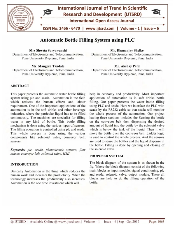
International Journal of Trend in Scientific Research and Development (IJTSRD) Volume 3 Issue 5, August 2019 Available Online: www.ijtsrd.com e-ISSN: 2456 – 6470 Liquid Level and Photoelectric Sensors Based Automatic Liquid Mixing and Filling Machine System using PLC Aye Aye Mar1, Hay Man Oo2, Kyawt Kyawt Hlaing1 1Lecturer, Department of Electronic Engineering, Technological University, Monywa, Myanmar 2Lecturer, Department of Electronic Engineering, Technological University, Meiktila, Myanmar How to cite this paper: Aye Aye Mar | Hay Man Oo | Kyawt Kyawt Hlaing "Liquid Level and Photoelectric Sensors Based Automatic Liquid Mixing and Filling Machine System using PLC" Published in International Journal of Trend in Scientific Research and Development (ijtsrd), ISSN: 2456- 6470, Volume-3 | Issue-5, August 2019, pp.1950-1954, https://doi.org/10.31142/ijtsrd27835 Copyright © 2019 by author(s) and International Journal of Trend in Scientific Research and Development Journal. This is an Open Access article distributed under the terms of the Creative Commons Attribution License (CC (http://creativecommons.org/licenses/by /4.0) I. INTRODUCTION Automation is used for all control systems and Programmable Logic Controller (PLC) technologies are used to reduce the human work and helps in increasing the production. By using PLC, there are many advantages such as safety cost and reducing space as software devices are used instead of hardware devices, easily repairing errors by using computer, quickly and exactly operating activities, increasing efficient production and reducing human efforts. The PLC plays an important role in the world of automation industry. The mixing operation is based on the user defined volume through which user can choose the volume of liquid to be mixed. Two liquid level sensors which are placed beside the mixer tank are used to sense the liquid level placed under the mixer motor and the corresponding mixer motor is switched on to mix the juice and water in the mixer tank. The filling operation is based on the user defined volume through which user can choose the volume of liquid to be filled. A photoelectric sensor which is placed in the conveyor, is used to sense the cup placed under the pump motor and the corresponding pump motor is switched on to fill the cup. This paper is based on that two liquids are mixed and filled into the cup using PLC automatically. In earlier days, when the two liquids are mixed and filled by humans, these two liquids are not mixed and filled in equal proportion. So, there is no precision of work. By using PLC, two liquids are mixed and filled in equal proportion and well quantity. This avoids wastage of liquids and reduces human efforts. Todays, ABSTRACT Today the application of PLC is more widely used in the digital world. There are many applications of PLC especially in the industrial. Normally, the PLCs that have been used at the industrial field are usually to control the machine or heavy machine in order to create an efficient production process. In this paper, a discussion about PLC application will be explained in more details and specified. A machine that uses to prepare automatic liquid mixing and filling machine system is controlled by Delta PLC which is also the heart of the entire system. The DVP-14SS2 from the Delta PLC types is used and WPL soft is used to write the ladder logic. The PLC can control many other electronic devices such as pump motor, level sensors, photoelectric sensor, conveyor belt, gear motor, solenoid valve, push buttons, relays and other devices. The main aim of the paper is to develop and test the real time implementation of PLC based liquid mixing and filling machine system. Firstly, start button is pushed. The liquids (juice and water) are mixed in the mixer tank by using valves. The level sensors know limited liquid levels and mixer motor starts stirring. The mixer motor is ON by timer. When the stirring process stops, the conveyor belt starts moving. When the cup passes photoelectric sensor, conveyor belt stops and then the pump motor fills the liquid mixture in the cup by timer. When the cup completes filling process, the pump motor closes and conveyor belt runs continuously. When another cup passes the photoelectric sensor, conveyor belt stops. Filling process operates again and again. KEYWORDS: Delta PLC, Level sensors, Photoelectric sensor, Valves, Mixer motor, Conveyor belt, Pump motor, Relay automatic liquid mixing and filling machine is used in the industrial fields. II. System Block Diagram To solve the problem, this liquid level and photoelectric sensors based automatic mixing and filling using Programmable Logic Controller(PLC) system is very convenient. The system for this paper is constructed with liquid level and photoelectric sensors for the input section and valves, mixer motor, conveyor motor and pump motor for the liquid mixing and filling machine system. The input section involves level sensors and photoelectric sensor. The 24V DC power supports to the PLC and 12V DC power supports to the pump motor. AC supply voltage SMPS 24 V DC IJTSRD27835 BY 4.0) Relay Valve 1 230VAC 50HZ Relay Valve 2 Photoelectric Sensor Delta PLC Mixer motor Relay Lower level sensor ( Programmable Logic Controller) Upper level sensor Conveyor motor Relay Start button Pump motor Relay Stop button Fig1: Overall Block Diagram of the System @ IJTSRD | Unique Paper ID – IJTSRD27835 | Volume – 3 | Issue – 5 | July - August 2019 Page 1950
International Journal of Trend in Scientific Research and Development (IJTSRD) @ www.ijtsrd.com eISSN: 2456-6470 When the start button is pressed, the power supply is applied to the PLC. The PLC commands the whole system by the program. Relays are used as drivers or switch to produce desired outputs. The liquids (juice and water) are mixed in a mixer tank by using valves. Then, Level sensors know limited liquid levels and mixer motor starts to stir. When mixer motor stops, conveyor motor starts to run and the desired cup put in a sequence on it. When the cup passes the photoelectric sensor, the conveyor belt stops and then pump motor fills the mixing liquid in the cup. When the cup completes filling process, the pump motor is closed and the conveyor belt continuously runs and carries the cup away from photoelectric sensor. When another cup passes the photoelectric sensor, then the above process is repeated. Fig.1 shows the overall block diagram of the system. Step 3: Check lower level sensor. If the juice level is specified lower level sensor, Valve 1 is OFF and Valve 2 is ON. Then fill the water into mixer tank. Step 4: Check upper level sensor. If liquid level is specified upper level sensor, Valve 2 is OFF and mixer motor is ON for timer 8s.Then mixer motor is OFF and conveyor motor is ON. Step 5: Check photoelectric sensor. If the cup passes photoelectric sensor, the conveyor motor is OFF and pump motor is ON. The mixing liquid fills into the cup by four seconds. Step 7: Stop. III. Hardware Implementation The circuit is constructed with three main sections. The first section is two liquid level and photoelectric sensors which are the input section. In the second section, there is DC motors (gear, mixer), pump motor and valves (1, 2) which are the output section. And the last one is Delta PLC (DVP 14SS11R2). Start button (X0), stop button (X1), photoelectric sensor (X2), lower level sensor (X3) and upper level sensor (X4) are connected with PLC as input devices. Conveyor motor (Y0), mixer motor (Y1), pump motor (Y2), valve 1(Y5) and valve 2(Y4) are connected with PLC as output devices. Fig3: Overall Circuit Diagram of the System For conveyor motor and mixer motor, 24 V (SMPS) is used. For pump motor, 12 V power supply is used. The lower/upper level sensors are connected to X3 and X4 of the PLC respectively for the two different liquid are mixed in equal proportion. The photoelectric sensor is connected to X2 of PLC for cup filling. The DC motors (gear, mixer), submersible pump motor and solenoid valves (1,2) are used for liquid mixing and cup filling in this operation. Relays are used as driver or switches to produce desired voltage. And then, the whole system is based on ladder diagram language software to operate the hardware structure. The ladder diagram language for the liquid mixing and filling system is based on ladder diagram language software (WPL soft 2.41). When the start button (X0) is pressed, the relay 5 is switched Fig2: Overall System Flowchart The flowchart shown in Fig.2 is for the operation of the system. In this system, the programmable logic controller (PLC) is used as the control system consists of Step 1: Start Step 2: Valve 1 is ON and fill the juice into the mixer tank. @ IJTSRD | Unique Paper ID – IJTSRD27835 | Volume – 3 | Issue – 5 | July - August 2019 Page 1951
International Journal of Trend in Scientific Research and Development (IJTSRD) @ www.ijtsrd.com eISSN: 2456-6470 on and the other relays are switched off. The output of relay 5 is connected to valve 1. And the juice flows in the mixer tank. When juice in the mixer tank passes the lower level sensor, the signal is reached to Delta PLC and the relay 5 is switched off. The output of relay 4 is connected to valve 2. During the relay 4 is switched on, the other relays are switched off. When the relay 4 is switched on, the water flows in the mixer tank. When the water in the mixer tank passes the upper level sensor (X4), the signal is reached to Delta PLC and the relay 4 is switched off. And then the mixer motor starts to stir. The output of relay 2 is connected to mixer motor (Y1). During the relay 2 is switched on, the other relays are switched off. After Stirring time (8s), the relay 2 is switched off and conveyor motor (Y0) which is connected to the output of relay 1 starts to run immediately. At that time, the empty cup is placed on the running conveyor belt. When empty cup passes the photoelectric sensor (X2), the signal is reached to Delta PLC and the relay 3 is switched on and other relays are switched off. The output of relay 3 is connected to pump motor. Pump motor (Y2) starts to fill liquid mixture into the empty cup with timer function. For filling process, the timer is limited by four seconds. When the liquid mixture is filled into the empty cup according to timer (4s), the relay 3 is switched off. Again the conveyor belt is running continuously, until the second cup passes photoelectric sensor. This system continuously runs until the stop button (X1) is pressed. IV. Results Simulation Result for level sensors The ladder programming language for lower level sensor is very simple. When X0(start button) is firstly pressed, S10 set. Difference of reset and zone-reset is: normal reset (RST) operates only one network, zone-reset (ZRST) operates the whole network group (example; S10, S20, as use as). As soon as, start point operates next step, the previous step automatically stops. When S10 set, M0 (tank-1 valve) starts. While M0 (tank-1 valve) is operating, X3 (liquid level sensor- 1) starts to detect. After X3 (lower level sensor-1) is detected, S11 set and M1 (tank-2 valve) starts to operate. Simulation Result for Motors The Ladder programming language is written as the simplest form so that it is nothing to have any problem to understand. Stirring time (T0) limits mixing time of two different liquids for eight seconds. After mixing time is finished, S13 set and M3 (conveyor motor) starts to run. Fig.6 shows the simulation of mixer flag. Fig 6: Simulation of Mixer Flag While M3 (conveyor motor) is running, X2 (photoelectric sensor) senses. Rising up is used for photoelectric sensor to sense only one cup-one time. As X2 (photoelectric sensor) senses the cup, M3 (conveyor motor) stops. Fig.7 shows the simulation of conveyor motor flag. Fig7: Simulation of Conveyor Motor Flag And then, S14 set and M4 (fill motor) starts to fill. Filling timer (T1) limits filling time of liquid mixture into the cup for four seconds. Fig 8: Simulation of Pump Motor Flag and Return After filling time is finished, S15 set and S13 set back to run M3(conveyor motor). Fig.8 shows the simulation of pump motor and return. Always connect RET instruction immediately after the last step point indicated as the above diagram otherwise program error may occur. Fig 4: Simulation of Lower Level Sensor (level sensor 1) Simulation of lower level sensor is shown in Fig.4. While M1 (tank-2 valve) is operating, X4 (upper level sensor-2) detect. After detecting, S12 set and M2 (mixer motor) starts to stir. Fig.5 shows the simulation of upper level sensor. Fig 8: Simulation of Pump Motor Flag and Return Hardware Results The operation is constructed with two liquid level sensors and the photoelectric sensor. The two liquid level sensors are placed beside the mixer tank and the photoelectric sensor is placed in the middle of the conveyor belt. But the lower/upper level sensors are connected to X3 and X4 of the PLC respectively for mixing the two different liquids in equal proportion. The photoelectric sensor is connected to X3 of PLC for bottle filling. The DC motors (gear, mixer), pump motor and solenoid valves (1,2) are used for liquid mixing Fig 5: Simulation of Upper Level Sensor (level sensor 2) @ IJTSRD | Unique Paper ID – IJTSRD27835 | Volume – 3 | Issue – 5 | July - August 2019 Page 1952
International Journal of Trend in Scientific Research and Development (IJTSRD) @ www.ijtsrd.com eISSN: 2456-6470 and filling in this operation. These are connected to Y0, Y1, Y2, Y5, and Y4 of the PLC respectively. When the start button is pressed, the solenoid valve-1 is opened to fill the juice into the mixer tank. Solenoid valves (flow control valves) are connected to the liquid tanks. These valves are electromagnetic plunger valves which control flow rate of liquid. Level sensors are placed beside the mixer tank. When the juice in the mixer tank passes the lower level sensor, liquid level sensor-1 senses it and the solenoid valve-1 is closed. After stirring process, the conveyor belt which is connected to gear motor start to run immediately. At that time, the empty cup is placed on the running conveyor belt. The photoelectric sensor is placed in the middle of the conveyor. The reflection with reflector type of the photoelectric sensor is used. It detects an object by using light. When empty cup passes the photoelectric sensor, it is sensed by sensor. Fig 9: Result for Solenoid valve-1 Fig12: Result for Photoelectric Sensor and Pump Motor And then, conveyor belt (motor-2) is stop. Pump motor (motor-3) starts to fill liquid mixture into the empty cup with timer function. For filling process, timer (T2) is limited by four seconds. When mixed liquid is filled into the empty cup according to timer (T2), the conveyor run continuously. Second cup is sensed by photoelectric sensor and conveyor motor stop. Filling process operates again and again. In this way, this process continuously run till stop button is pressed. Fig.13 shows the overall result of automatic liquid mixing and filling machine system. And then solenoid valve-2 is opened to fill the water into the mixer tank. If the liquid in the mixer tank passes the upper level sensor, the liquid level sensor-2 senses it and then, this valve-2 is closed. DC motors were used to stir the juice and water, to move conveyor forward and to fill the liquid mixture into empty cup. Fig 10: Result for Lower Level Sensor and Solenoid valve-2 As soon as valve-2 has closed, the mixer motor starts to stir the juice and water in the mixer tank. Mixer motor stirs the juice and water in the mixer tank by eight seconds. Fig13: Result for Overview of Liquid Mixing and Filling Machine System V. Conclusion The PLC is used in this system to get more productivity with less time, high reliability and flexible in work. The ladder diagram language using totally integrated automation portal software (WPL soft 2.41) is used in this paper because this language is very useful to run all types of industrial applications and has a lot of functions so that most of the Fig 11: Result for Upper Level Sensor and Mixer Motor @ IJTSRD | Unique Paper ID – IJTSRD27835 | Volume – 3 | Issue – 5 | July - August 2019 Page 1953
International Journal of Trend in Scientific Research and Development (IJTSRD) @ www.ijtsrd.com eISSN: 2456-6470 industrial application uses this language. This system also use very low power consumption because PLC only use 24VDC to operate their input and output device. The cost of installation is not cheap but it can efficiently run for a long period of time. This automation system is used to reduce workers and help in increasing the mass production. VI. REFERENCES [1]Timber crest, “Practical Guide to Programmable Logic Controllers” (Aug21, Library.automationdirect.com>plc. [8]Carlos Gonzalez, “Machine Design Engineering Essentials: What is a Programmable Logic controller?” , June 01,2015 [9]DipaliChaudhari, Topmost 12 “Different PLC software Brands used around the world”, August 10 , 2018 [10]Jacob Fraden, “Handbook of modern sensors” – KELM (1993) www.kelm.ftn.uns.ac.rs>lite ratura.pdf [11]KELLER,“OEM Instrumentation” www.wolfautomation.com>pdf>takex. Pressure (Oct Measurement 1, 2018), https:// 2000) [2]Shaukat N., “PLC Based Automatic Liquid Filling Process,” IEEE, [12]Balluff, “Photoelectric Sensor Handbook”(Sep19, 2016) https:// www.machine design.com>sensors. [3]Multi Topic Conference, 2002. [13]Philip L. Skousen“ Valve Handbook” (1997) [4]Positite. M. “Omron Beginner’s guide to PLC", www.mikrocontrol.co. yu, Serbia, 2003, pp 1-17 [14]Bob. Flesher “Relays Handbook”.(1997) [15]Billd700, “Different types of motors and their use” (May 5, 2016). online.com>designspark. [5]Nabil Shaukat, “A PLC Based Automatic Liquid Filling Process”, IEEE, publication page No. 226-233, 2002. https:// www.rs- [6]Xi Chen, YanboChe, K.W.E Cheng, “PLC and Configuration Software Based Supervisory and Control System for Oil Tanks Area”, Digital Reference: K210509077, 2009, 3rd International Conference on Power Electronics Systems and Application [16]Sbasish Ghosh, “Synchronous Motor Working Principle” (Jul 7,2013) https:// www.electrical 4u.com [17]Tarun Agarwal: Servo Motor: Basic, Theory and Working Principle, 2015. [7]Smith, C L “Process Control for the process Industries- Part 2: Steady State Characteristics”. March 2017 @ IJTSRD | Unique Paper ID – IJTSRD27835 | Volume – 3 | Issue – 5 | July - August 2019 Page 1954