Download
1 / 4
40 likes | 255 Vues
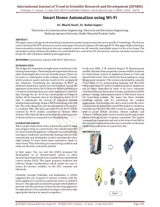
This paper aims to design an Advanced home automation system using normal web server and Wi Fi technology. The devices can be switched ON OFF and sensors can be read using a Personal Computer PC through Wi Fi. This paper helps to develop a home automation system that gives the user complete control over all remotely controllable aspects of his or her home. The automation system will have the ability to be controlled from a central host PC, the Internet, and also remotely accessed via a Pocket PC with a Windows Mobile based application. Er. Bharti Sood | Er. Rahul Gupta "Smart Home Automation using Wi-Fi" Published in International Journal of Trend in Scientific Research and Development (ijtsrd), ISSN: 2456-6470, Volume-3 | Issue-2 , February 2019, URL: https://www.ijtsrd.com/papers/ijtsrd21372.pdf Paper URL: https://www.ijtsrd.com/engineering/electronics-and-communication-engineering/21372/smart-home-automation-using-wi-fi/er-bharti-sood<br>

E N D
International Journal of Trend in Scientific Research and Development (IJTSRD) Volume: 3 | Issue: 2 | Jan-Feb 2019 Available Online: www.ijtsrd.com e-ISSN: 2456 - 6470 Smart Home Automation using Wi-Fi Er. Bharti Sood1, Er. Rahul Gupta2 1Electronics & Communications Engineering, 2Electrical and Electronics Engineering, Maharaja Agrasen University, Baddi, Himachal Pradesh, India ABSTRACT This paper aims to design an Advanced home automation system using normal web server and Wi-Fi technology. The devices can be switched ON/OFF and sensors can be read using a Personal Computer (PC) through Wi-Fi. This paper helps to develop a home automation system that gives the user complete control over all remotely controllable aspects of his or her home. The automation system will have the ability to be controlled from a central host PC, the Internet, and also remotely accessed via a Pocket PC with a Windows Mobile based application. KEYWORDS: Automation, Arduino UNO, Wi-Fi, Web Server INTRODUCTION The hunger for automation brought many revolutions in the existing technologies. These had greater importance than any other technologies due to its user-friendly nature. These can be used as a replacement of the existing switches in home which produces sparks and also results in fire accidents in few situations. Considering the advantages of Wi-Fi an advanced automation system was developed to control the appliances in the house. Wi-Fi (Short for Wireless Fidelity) is a wireless technology that uses radio frequency to transmit data through the air. Wi-Fi has initial speeds of 1mbps to 2mbps. Wi-Fi transmits data in the frequency band of 2.4 GHz. It implements the concept of frequency division multiplexing technology. Range of Wi-Fi technology is 40-300 feet. The controlling device for the automation in the project is a Arduino UNO. The data sent from PC over Wi-Fi will be received by Wi-Fi module connected to Arduino UNO. Arduino UNO reads the data and decides the switching action of electrical devices connected to it through Relays. LITERATURE SURVEY When people think about home automation, most of them may imagine living in a smart home: One remote controller for every household appliance, cooking the rice automatically, starting air conditioner automatically, heating water for bath automatically and shading the window automatically when night coming. To some extent home automation equals to smart home. They both bring out smart living condition and make our life more convenient and fast. In their paper, Tan, Lee and Soh (2002) proposed the development of an Internet-based system to allow monitoring of important process variables from a distributed control system (DCS). This paper proposes hardware and software design considerations which enable the user to access the process variables on the DCS, remotely and effectively. Potamitis, Georgila, Fakotakis, and Kokkinakis, G. (2003) suggested the use of speech to interact remotely with the home appliances to perform a particular action on behalf of the user. The approach is inclined for people with disability to perform real-life operations at home by directing appliances through speech. Voice separation strategy is selected to take appropriate decision by speech recognition. In the year 2006 , S. M. Anamul Haque,S. M. Kamruzzaman and Md. Ashraful Islam proposed a system entitled “A System for Smart-Home Control of Appliances Based on Time and Speech Interaction” that controls the home appliances using the personal computer. This system is developed by using the Visual Basic 6.0 as programming language and Microsoft voice engine tools for speech recognition purpose. Appliances can be either controlled by timer or by voice command. Ciubotaru Petrescu, Chiciudean, Cioarga, and Stanescu (2006) present a design and implementation of SMS based control for monitoring systems. The paper has three modules involving sensing unit for monitoring the complex applications. A processing unit, that is microcontroller and a communication module that uses GPRS modem or cell phone via serial port RS-232. The SMS is used for status reporting such as power failure. Jawarkar, Ahmed, Ladhake, and Thakare (2008) propose remote monitoring through mobile phone involving the use of spoken commands. The spoken commands are generated and sent in the form of text SMS to the control system and then the microcontroller on the basis of SMS takes a decision of a particular task. METHODOLOGY @ IJTSRD | Unique Reference Paper ID – IJTSRD21372 | Volume – 3 | Issue – 2 | Jan-Feb 2019 Page: 396
International Journal of Trend in Scientific Research and Development (IJTSRD) @ www.ijtsrd.com eISSN: 2456-6470 Hardware description Arduino:- The Arduino Uno is a microcontroller board based on the ATmega328 (datasheet). It has 14 digital input/output pins (of which 6 can be used as PWM outputs), 6 analog inputs, a 16 MHz ceramic resonator, a USB connection, a power jack, an ICSP header, and a reset button. It contains everything needed to support the microcontroller; simply connect it to a computer with a USB cable or power it with a AC-to-DC adapter or battery to get started. The Uno differs from all preceding boards in that it does not use the FTDI USB- to-serial driver chip. Instead, it features the Atmega16U2 (Atmega8U2 up to version R2) programmed as a USB-to-serial converter. Uno" means one in Italian and was chosen to mark the release of Arduino Software (IDE) 1.0. The Uno board and version 1.0 of Arduino Software (IDE) were the reference versions of Arduino, now evolved to newer releases. The Uno board is the first in a series of USB Arduino boards. necessary to control a circuit by a separate low power signal, or where several circuits must be controlled by one signal. Relay was used extensively in telephone exchange and early computers to perform logical operation. A type of relay that can handle the high power required to directly control an electronic motor or other loads is called a contactor. Solid state relay controls power circuit with no moving parts, instead using a semiconductor device to perform switching. Relay calibrated operating characteristics and sometimes multiple operating coil are used to protect electrical circuits from overload or faults; in modern electric power system these functions are performed by digital instruments still called “protective relay”. Circuit Diagram Fig- 4 Circuit Diagram for bulb and fan Fig 2 – Arduino Uno ESP8266 Wifi Module The ESP8266 is a low cost Wi-Fi chip with full TCP/IP stack and microcontroller unit. This small module allows microcontroller to connect to a Wi-Fi network and make simple TCP/IP connection using Hayes style commands, The ESP8266 with 1MiB of built in flash, allowing for single chip device capable of connecting to Wi-Fi. Figure 4 shows theESP8266 module structure. Fig 5 – Circuit Diagram For Automated Door Software:-Arduino IDE:- In this we will get know of the process of installation of Arduino IDE and connectingArduino uno to Arduino IDE. Step 1 - First we must have our Arduino board (we can choose our favorite board) and a USB cable. In case we use Arduino UNO, Arduino Duemilanove, Nano, Arduino Mega 2560, or Diecimila, we will need a standard USB cable (A plug to B plug), In case we use Arduino Nano, we will need an A to Mini-B cable. Fig 3 – ESP8266 Wifi Module Relay Board A relay is an electrically operated switch. Many relay use an electromagnet to, mechanically operates a switch, but other operating principles are also used, such as solid state relay. Relay are used where it is @ IJTSRD | Unique Reference Paper ID – IJTSRD21372 | Volume – 3 | Issue – 2 | Jan-Feb 2019 Page: 397
International Journal of Trend in Scientific Research and Development (IJTSRD) @ www.ijtsrd.com eISSN: 2456-6470 Step 2 Step 5 − Open our ?irst project. Once the software starts, we have two options ?Create a new project ?Open an existing project example. To create a new project, select File → New. To open an existing project example, select File → Example → Basics → Blink. Here, we are selecting just one of the examples with the name Blink. It turns thED on and off with some time delay. We can select any other example from the list. Fig 6 - Unziping Arduino IDE Download Arduino IDE Software. We can get different versions of Arduino IDE from. the Download page on the Arduino Official website. We must select software, which is compatible with wer operating system (Windows, IOS, or Linux). After file download is complete, unzip the file. Step 3 − Power up our board The Arduino Uno, Mega, Duemilanove and Arduino Nano automatically draw power from either, the USB connection to the computer or an external power supply. If we are using an Arduino Diecimila, we have to make sure that the board is configured to draw power from the USB connection. The power source is selected with a jumper, a small piece of plastic that fits onto two of the three pins between the USB and power jacks. Check that it is on the two pins closest to the USB port. Connect the Arduino board to wer computer using the USB cable. The green power LED (labeled PWR) should glow. Step 4 − Launch Arduino IDE. After our Arduino IDE software is downloaded, we need to unzip the folder. Inside the folder, we can find the application icon with (application.exe). Double- click the icon to start the IDE. Fig 8 – Creating New Project Step 6 − Select our Arduino board. To avoid any error while uploading program to the board, we must select the correct Arduino board name, which matches with the board connected to computer Go to Tools → Board and select board. Here, we have selected Arduino Uno board according to our tutorial, but we must select the name matching the board that we are using. Step 7 − Select serial port. Select the Arduino board. Go to Tools → Serial Port menu. This is likely to be COM3 or higher (COM1 and COM2 are usually reserved for hardware serial ports). To find out, we can disconnect were Arduino board and re-open the menu, the entry that disappears should be of the Arduino board. Reconnect the board and select that serial port. an infinity label Fig 7 – Lunching Arduino IDE Fig 9 – Selecting Port @ IJTSRD | Unique Reference Paper ID – IJTSRD21372 | Volume – 3 | Issue – 2 | Jan-Feb 2019 Page: 398
International Journal of Trend in Scientific Research and Development (IJTSRD) @ www.ijtsrd.com eISSN: 2456-6470 Step 8 − Upload the program to board. Before explaining how we can upload our program to the board, we must demonstrate the function of each symbol appearing in the Arduino IDE toolbar. References [1]Sharma, Raj., Chirag, Pranjalkatara, Shankar, Vishnu. Proceedings of IEEE TechSym 2014 Satellite Conference VIT University, Paper on Advanced Low- Cost Security system using sensors, Arduino and GSM communication module. [2]DeepaliJavale, Mohd., Mohsen, Nandewar, Shreerang., MayurShingate. (2013). Home Automation and Security using Android ADK, (March). [3]Yavuz, E., Hasan, B., Serkan, I., Duygu, K. (2007). Safe and Secure PIC Based Remote Control Application for Intelligent Home, 7 (5) (May). Fig 10 - Toolbar A − Used to check if there is any compilation error, B − Used to upload a program to the Arduino board. C − Shortcut used to create a new sketch. D − Used to directly open one of the example sketch. E − Used to save sketch. F − Serial monitor used to receive. Now, simply click the "Upload" button in the environment. Wait a few seconds; we will see the RX and TX LEDs on the board, flashing. If the upload is successful, the message "Done uploading" will appear in the status bar. Serial data from the board and send the serial data to the board. Conclusions In this paper, a novel architecture for low cost and flexible home Automation system using Arduino microcontroller is proposed and implemented. Overall Arduino is easy to understand & its coding is easy. By implementing this type of system we can ensure that the energy conservation can be done. By help of this system we can increase the efficiency of the appliances .we can have the complete control over the home appliances from a long distance. This will Increase the comfort ability of human being and it will reduce the Human efforts. [4]Sriskanthan, N., Karand, Tan. (2002). Bluetooth Based Home Automation Microprocessors and Microsystems, Vol. a. 26. p.281- 289. System. Journal of [5]Kusuma, S. Department of telecommunication, MSRIT, Bangalore, India. Home Automation Using Internet of Things. (July). M. (1999). Assistant Professor, [6]Niharika Shrotriya, Kulkarni, Anjali., PritiGadhave. (1996). SMART HOME USING WI-FI, International Journal of Science, Engineering and Technology Research (IJSETR). [7]Anu shri, Aware. Vaidya, Sonali., Ashture, Priyanka., Gaiwal, Varsha. (1991). PES’s Modern College of Engineering, Pune-04, International Journal of Engineering Research and General Science, Volume 3, Home Automation using Cloud Network. (February) @ IJTSRD | Unique Reference Paper ID – IJTSRD21372 | Volume – 3 | Issue – 2 | Jan-Feb 2019 Page: 399