Download
1 / 5
50 likes | 68 Vues
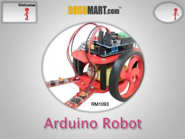
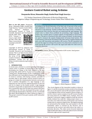
This paper investigates based on Arduino voice generator text to speech robot. Voice generator text to speech robot system is very beneficial in areas where there is high risk for humans to enter. Voice generator text to speech robot system is controlled voice commands. The integration of the control unit with the Bluetooth device is achieved using a Bluetooth module to capture and read the voice commands. The controlling device may be any smartphone. The transmitter uses an android application required for transmitting the data. The receiver end reads these commands and interprets them into controlling the robotic vehicle. The android application sends commands to move the vehicle in forward, backward, left and right directions. Then, stop commands to stop the vehicle. After receiving the commands, Arduino operates the motors in order to move the vehicle in four directions and stop. The communication between android application and receiver is sent as serial communication data. Arduino program is designed to move the motor through a motor driver circuit as per the commands. The camera is interfaced to record the forward movement of the robot system which also includes night vision camera which will not only allow viewing whatever will be recorded in day time but also during the night. Hay Man Oo | Ni Ni San Hlaing | Thin Thin Oo "Arduino Based Voice Generator Text to Speech Robot" Published in International Journal of Trend in Scientific Research and Development (ijtsrd), ISSN: 2456-6470, Volume-3 | Issue-5 , August 2019, URL: https://www.ijtsrd.com/papers/ijtsrd26632.pdf Paper URL: https://www.ijtsrd.com/engineering/electronics-and-communication-engineering/26632/arduino-based-voice-generator-text-to-speech-robot/hay-man-oo<br>

E N D
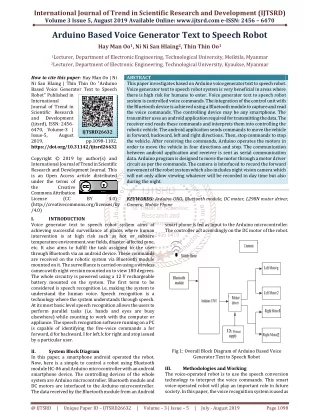
International Journal of Trend in Scientific Research and Development (IJTSRD) Volume 3 Issue 5, August 2019 Available Online: www.ijtsrd.com e-ISSN: 2456 – 6470 Arduino Based Voice Generator Text to Speech Robot Hay Man Oo1, Ni Ni San Hlaing2, Thin Thin Oo1 1Lecturer, Department of Electronic Engineering, Technological University, Meiktila, Myanmar 2Lecturer, Department of Electronic Engineering, Technological University, Kyaukse, Myanmar How to cite this paper: Hay Man Oo | Ni Ni San Hlaing | Thin Thin Oo "Arduino Based Voice Generator Text to Speech Robot" Published in International Journal of Trend in Scientific Research and Development (ijtsrd), ISSN: 2456- 6470, Volume-3 | Issue-5, August 2019, https://doi.org/10.31142/ijtsrd26632 Copyright © 2019 by author(s) and International Journal of Trend in Scientific Research and Development Journal. This is an Open Access article distributed under the terms of the Creative Commons Attribution License (CC (http://creativecommons.org/licenses/by /4.0) I. INTRODUCTION Voice generator text to speech robot system aims at achieving successful surveillance at places where human intervention is at high risk such as hot or subzero temperature environment, war fields, disaster-affected zone, etc. It also aims to fulfill the task assigned to the user through Bluetooth via an android device. These commands are received on the robotic system via Bluetooth module mounted on it. The surveillance is carried on using a wireless camera with night version mounted on to view 180 degrees. The whole circuitry is powered using a 12 V rechargeable battery mounted on the system. The first term to be considered is speech recognition i.e, making the system to understand the human voice. Speech recognition is a technology where the system understands through speech. At its most basic level speech recognition allows the users to perform parallel tasks (i.e. hands and eyes are busy elsewhere) while counting to work with the computer or appliance. The speech recognition software running on a PC is capable of identifying the five-voice commands a for forward, d for backward, I for left, k for right and stop issued by a particular user. II. System Block Diagram In this paper, a smartphone android operated the robot. Now, here is a simple to control a robot using Bluetooth module HC-06 and Arduino microcontroller with an android smartphone device. The controlling devices of the whole system are Arduino microcontroller. Bluetooth module and DC motors are interfaced to the Arduino microcontroller. The data received by the Bluetooth module from an Android ABSTRACT This paper investigates based on Arduino voice generator text to speech robot. Voice generator text to speech robot system is very beneficial in areas where there is high risk for humans to enter. Voice generator text to speech robot system is controlled voice commands. The integration of the control unit with the Bluetooth device is achieved using a Bluetooth module to capture and read the voice commands. The controlling device may be any smartphone. The transmitter uses an android application required for transmitting the data. The receiver end reads these commands and interprets them into controlling the robotic vehicle. The android application sends commands to move the vehicle in forward, backward, left and right directions. Then, stop commands to stop the vehicle. After receiving the commands, Arduino operates the motors in order to move the vehicle in four directions and stop. The communication between android application and receiver is sent as serial communication data. Arduino program is designed to move the motor through a motor driver circuit as per the commands. The camera is interfaced to record the forward movement of the robot system which also includes night vision camera which will not only allow viewing whatever will be recorded in day time but also during the night. KEYWORDS: Arduino UNO, Bluetooth module, DC motor, L298N motor driver, Camera, Mobile Phone IJTSRD26632 pp.1098-1102, BY 4.0) smart phone is fed as input to the Arduino microcontroller. The controller act accordingly on the DC motor of the robot. Fig 1: Overall Block Diagram of Arduino Based Voice Generator Text to Speech Robot III. The voice-operated robot is to use the speech conversion technology to interpret the voice commands. This smart voice-operated robot will play an important role in future society. In this paper, the voice recognition system is used as Methodologies and Working @ IJTSRD | Unique Paper ID – IJTSRD26632 | Volume – 3 | Issue – 5 | July - August 2019 Page 1098
International Journal of Trend in Scientific Research and Development (IJTSRD) @ www.ijtsrd.com eISSN: 2456-6470 the user interface to operate the system. Firstly, the user has to give voice commands via android smartphone which will be with the user only. These commands are processed in the smartphones and according to signals are then sent to Bluetooth modem which is connected to the Arduino board. The robot is operated by two DC motors. The Arduino operates these DC motors via IC L298D and controls the robot accordingly. The voice commands are a for forward, d for backward, I for left, k for right and stop. Software Implementation for HC-06 Bluetooth Module The software implementation for HC-06 is very simple. This function will follow the declaration of serial port between mobile devices and microcontroller. Serial.begin(9600); This function opens a virtual serial port with 9600 baud rate. Baud rate is the rate between serial ports. Google voice from mobile devices converts the incoming voice command to text and then sends the text to the microcontroller system via a serial port. It is essential in the voice generator text to speech robot. Serial.readString() is used to get voice command from a mobile device and checked whether the motor is forward, backward, left or right. While (Serial.available()) { a=Serial.readtring(); Serial.println(a); If (a= = “a”) { //Codes for motor driver } If (a= = “d”) { //Codes for motor driver } If (a= = “I”) { //Codes for motor driver } If (a= = “k”) { //Codes for motor driver } If (a= = “stop”) { //Codes for motor driver } } Software Implementation for DC Motor Driver Motor’s outputs are connected to the L298N motor driver. It is output by using to set pinMode and defined program variables namely LM1 for the left motor1, LM2 for the left motor2, RM1 for the right motor1 and RM2 for the right motor 2. define LM1 2 define LM1 3 define RM1 4 define RM1 5 The speed of the DC motor is controlled by PWM also called Pulse Width Modulation. Digital pin 9 and pin 10 are PWM pins of the microcontroller. define speed A 9 define speed B 10 After defining the pin number, it’s declared the pin outputs with the following codes. pinMode(LM1, OUTPUT); pinMode(LM2, OUTPUT); pinMode(RM1, OUTPUT); pinMode(RM2, OUTPUT); pinMode(speedA, OUTPUT); pinMode(speedB, OUTPUT); For the motor drive, the speed of the motor is controlled by analog value. Analog is 8-bit resolution and 2 to the power 8 is equal to 256 and 0 to 255. So, it can adjust the speed value with the analogWrite function. Fig 2: Flowchart of Arduino Based Voice Generator Text to Speech Robot IV. Implementation A. Software Implementation The software implementation is the Arduino IDE based software environment. A program written with the Arduino IDE is called a sketch. Sketches are saved on the development computer as text files with the file extension .ino. Arduino Software (IDE) saved sketches with the extension .pde. A minimal Arduino C/C++ program consists of only two functions: setup (): This function is called once when a sketch starts after power-up or reset. It is used to initialize variables, input and output pin modes, and other libraries needed in the sketch. Loop (): After setup () function exits (ends), the loop () function is executed repeatedly in the main program. It controls the board until the board is powered off or is reset. @ IJTSRD | Unique Paper ID – IJTSRD26632 | Volume – 3 | Issue – 5 | July - August 2019 Page 1099
International Journal of Trend in Scientific Research and Development (IJTSRD) @ www.ijtsrd.com eISSN: 2456-6470 analogWrite(speed A, 102); analogWrite(speed B, 102); Bluetooth device is achieved using a Bluetooth module to capture and read the voice commands. The robotic vehicle operates as per the command received via android device, for this Arduino is integrated into the system. The controlling device may be any smartphone having an Android application. The android device sends commands for forward, backward, right, left and stop conditions. After receiving the commands, Arduino operates the motors in order to move the vehicle in five conditions. Arduino program is designed to move the motor through a motor driver circuit as per the commands sent by the android device. The camera is interfaced to record the forward movement of the robotic system which also includes night vision camera which not only allows viewing whatever recode in day time but also during the night. The whole circuitry is powered using a 12 V rechargeable battery mounted on the system. Software implementation for the motor’s forward direction For the motor’s forward direction, it is coded with digitalWrite functions. digitalWrite(LM1, HIGH); digitalWrite(LM2, LOW); digitalWrite(RM1, HIGH); digitalWrite(RM2, LOW); Software implementation for the motor’s reverse Direction For the motor’s reverse direction, it is coded with digitalWrite functions. digitalWrite(LM1, LOW); digitalWrite(LM2, HIGH); digitalWrite(RM1, LOW); digitalWrite(RM2, HIGH); Software implementation for the motor’s left direction For the motor’s left direction, it is coded with digitalWrite functions. digitalWrite(LM1, HIGH); digitalWrite(LM2, LOW); digitalWrite(RM1, LOW); digitalWrite(RM2, LOW); Software implementation for the motor’s right direction For the motor’s right direction, it is coded with digitalWrite functions. digitalWrite(LM1, LOW); digitalWrite(LM2, LOW); digitalWrite(RM1, HIGH); digitalWrite(RM2, LOW); Software implementation for the motor’s stop For the motor’s stop, it is coded with digitalWrite functions. digitalWrite(LM1, LOW); digitalWrite(LM2, LOW); digitalWrite(RM1, LOW); digitalWrite(RM2, LOW); Fig 3: Overall Circuit Diagram of Arduino Based Voice Generator Text to Speech Robot V. This section is test and results of the whole system. Attesting of result percentage of accuracy speech recognition, the speech recognition is achieved by the use of Arduino board with the Bluetooth wireless interface of the smartphone. And the output is generated by the system which has accuracy about 90% i.e, after 1 and 2 seconds the voice command is followed by the robotic system and the system moves right, left, forward, backward according to commands and stops. At the description of this section includes six parts of the test and results. Results B. This circuit is constructed with three main sections. The first section is the Bluetooth module which is the input section. The second one is the motor driver which are the output section. And the last one is the microcontroller Arduino UNO. The transmit of the Bluetooth module is connected to digital pin 0 and the receiver of the Bluetooth module is connected to digital pin 1 of the Arduino board for transmit and receive. The power supply of the Bluetooth module is connected to 5 V and ground of the Bluetooth module is connected to the ground pin of the Arduino. Hardware Implementation Table1. Result Percentage of Accuracy Speech Recognition Number of tests correct tests k for Right 10 I for Left 10 d for Backward a for Forward Stop 10 The first and second motors are placed together at the left side of the robot, the third and fourth motors are placed together at the right side of the robot. The first and second motors are connected to M1 of the motor driver and the third and fourth motors are connected to M2 of the motor driver. Enable A and B of the motor driver are connected to digital pin 9 and digital pin 10 for the output. The input 1 and 2 of the motor driver are connected to digital pin 2 and digital pin 3 for the left motor. The input 3 and 4 of the motor driver are connected to digital pin 4 and digital pin 5 for the right motor. The integration of control unit with Number of a Percentage of accuracy 90% 90% Data Given 9 9 10 9 90% 10 10 100% 10 100% @ IJTSRD | Unique Paper ID – IJTSRD26632 | Volume – 3 | Issue – 5 | July - August 2019 Page 1100
International Journal of Trend in Scientific Research and Development (IJTSRD) @ www.ijtsrd.com eISSN: 2456-6470 Robot Move Testing for forwarding Condition When a user gives the command a, robot moves in the given command direction. Fig: 7. shows testing of the right condition. Robot Testing for Stop Condition Testing of stop condition occurs when the user gives command stop by android phone that will transmit and receive the information signals by giving commands it will stop in the given command condition. Fig: 4. shows the testing of the forward condition Robot Move Testing for Backward Condition Testing of backward condition occurs when the user gives command d by android phone that will transmit and receive the information signals by giving commands it will move in the given command direction. Fig: 8. shows testing of the stop condition. VI. The voice controlling commands are successfully transmitted via Bluetooth technology and on reception the desired operations successfully take place. This paper reduces human efforts in places or situations where human interventions are difficult. Such systems can be brought into use at places such as industries, military and defense, research purposes, etc. The outcome of the thesis is a simple robot which is controlled the voice commands. This paper aims to provide simple guidelines for people interested in building robots. The voice recognition software has accuracy around 75% incorrectly identifying a voice command. But it is highly sensitive to the surrounding noises. There is a possibility of misinterpreting some noises as one of the voice commands given to the robot. Also, the accuracy of word recognition reduces in the face of the noise. The sound coming from motors has a significant effect on accuracy. There are some drawbacks in the mobile platform. The rechargeable 12 V batteries carried onboard makes it too heavy. Hence user had to use powerful motors to drive the robot making the power consumption higher. So the user had to recharge the batteries quite often. The mobile platform had some problems in turning due to the heaviness of itself. The backs freewheel used to get stuck when turning especially in reverse motion. Hence user suggests that steering mechanism may be a better option. The system is tested with different command sets and both the current user and other users. The results are quite satisfactory. Generally, the system recognizes the commands with 90% to Conclusion Fig: 5. shows testing of backward condition. Robot Move Testing for Left Condition This testing is robot move testing for the left condition of Arduino based voice generator text to speech robot. Fig: 6. shows the testing of the left condition. Robot Move Testing for Right Condition Testing of right condition occurs when the user gives command k by android phone that will transmit and receive the information signals by giving commands it will move in the given command direction. @ IJTSRD | Unique Paper ID – IJTSRD26632 | Volume – 3 | Issue – 5 | July - August 2019 Page 1101
International Journal of Trend in Scientific Research and Development (IJTSRD) @ www.ijtsrd.com eISSN: 2456-6470 [4]Subhash, P., Rasal, M. and Phaltan.: Voice Controlled Robotic Vehicles, International Journal of New Trends in Electronics and Communication, Jan, (2014). 100% success ratios for the current user and 75% to 85% for other users. VII. REFERENCES [1]Narayana, M., Abhinay, A. and Harsha, C.: Voice Control Robot Using AndroidApplication, International Journal of Engineering Innovation & Research, (2015). [5]Nagamani, V., Shanti, Sreedhar, CH., Siddharth and Rakesh, A.: Voice-Activated Programmable Multipurpose Robot, International Journal of Advanced Research in Computer Engineering & Technology (IJARCET), July, (2013). [2]Garima. and Diksha.: Android Mobile Application Build On Eclipse, International Journal of Scientific and Research Publications, February, (2014). [6]Dovgan, D., Kaluža, B., Tušar, T. and Gams, M.: Agent- based Security System, International Joint Conference on Web Intelligence and Intelligent Agent Technology, (2009). [3]Selvakumar, J. and Kannan, K.: Arduino Based Voice Controlled Robot, International Research Journal of Engineering and Technology (IRJET) Internationals ISSN (Online): 2347-3878Volume 2 Issue 7, July, (2014). [7]Pires, G. and Nunes, U.: Wheelchair Steered Through Voice Commands, Journal of Intelligent and Robotic Systems, (2002). @ IJTSRD | Unique Paper ID – IJTSRD26632 | Volume – 3 | Issue – 5 | July - August 2019 Page 1102