Download
1 / 6
60 likes | 113 Vues
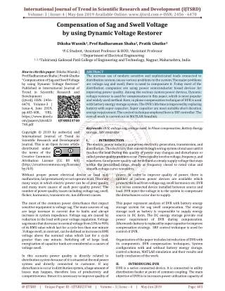
The increase use of modern sensitive and sophisticated loads connected to distribution system causes various problems to the system. The major problems are voltage sag and swell, there is need to compensate it .Today most of the distribution companies are using power semiconductor based devices for improving power quality. Among the various custom power devices, Dynamic voltage restorer is used for compensation in this paper, which is most popular and widely used method. Here, in phase compensation technique of DVR is used with battery energy storage system. The DVR's life time is improved by replacing battery with super capacitor. Super capacitor are most suitable short duration energy requirement. The control technique employed here is SRF controller. The overall work is carried out in MATLAB Simulink. Diksha Wasnik | Prof Radharaman Shaha | Pratik Ghutke "Compensation of Sag and Swell Voltage by using Dynamic Voltage Restorer" Published in International Journal of Trend in Scientific Research and Development (ijtsrd), ISSN: 2456-6470, Volume-3 | Issue-4 , June 2019, URL: https://www.ijtsrd.com/papers/ijtsrd23740.pdf Paper URL: https://www.ijtsrd.com/engineering/electrical-engineering/23740/compensation-of-sag-and-swell-voltage-by-using-dynamic-voltage-restorer/diksha-wasnik<br>

E N D
International Journal of Trend in Scientific Research and Development (IJTSRD) Volume: 3 | Issue: 4 | May-Jun 2019 Available Online: www.ijtsrd.com e-ISSN: 2456 - 6470 Compensation of Sag and Swell Voltage by using Dynamic Voltage Restorer Diksha Wasnik1, Prof Radharaman Shaha2, Pratik Ghutke3 1P.G Student, 2Assistant Professor & HOD, 3Assistant Professor 1,2Department of Electrical Engineering 1, 2, 3Tulsiramji Gaikwad Patil College of Engineering and Technology, Nagpur, Maharashtra, India How to cite this paper: Diksha Wasnik | Prof Radharaman Shaha | Pratik Ghutke "Compensation of Sag and Swell Voltage by using Dynamic Voltage Restorer" Published in International Journal of Trend in Scientific Research and Development (ijtsrd), ISSN: 2456- 6470, Volume-3 | Issue-4, June 2019, pp.403-408, URL: https://www.ijtsrd.c om/papers/ijtsrd23 740.pdf Copyright © 2019 by author(s) and International Journal of Trend in Scientific Research and Development Journal. This is an Open Access article distributed under the terms of the Creative Commons Attribution License (CC BY 4.0) (http://creativecommons.org/licenses/ by/4.0) Without proper power electrical device or load may malfunction, fail prematurely or not operate at all. There are many ways in which electric power can be of poor quality and many more causes of such poor quality power. The number of power quality issues including voltage sag, swell, flicker, harmonics, transients etc. has different causes. The most of the common power disturbance that impact sensitive equipment is voltage sag .The main sources of sag are large increase in current due to faults and abrupt increase in system impedance. Voltage sag are caused by reduction in the load with poor voltage regulation. Voltage sag means that decrease in normal voltage from 10% to 90% of its RMS value which last for a cycle less than one minute .Voltage swell, in contrast, can be defined as increase in RMS voltage above the nominal value which last for a cycle greater than one minute. Switching off of large load, energization of capacitor bank are considered as a causes of voltage swell. In this scenario power quality is directly related to distribution system because of it is situated at the end power system and directly connected to customer. If any disturbance is occur in distribution system, a huge amount of losses may happen, therefore loss of productivity and competitiveness. Hence it is necessary to improve quality of ABSTRACT The increase use of modern sensitive and sophisticated loads connected to distribution system causes various problems to the system. The major problems are voltage sag and swell, there is need to compensate it .Today most of the distribution companies are using power semiconductor based devices for improving power quality. Among the various custom power devices, Dynamic voltage restorer is used for compensation in this paper, which is most popular and widely used method. Here, in phase compensation technique of DVR is used with battery energy storage system. The DVR’s life time is improved by replacing battery with super capacitor. Super capacitor are most suitable short duration energy requirement. The control technique employed here is SRF controller. The overall work is carried out in MATLAB Simulink. Keywords: DVR, voltage sag, voltage swell, In Phase compensation, Battery Energy storage, SRF controller I. INTRODUCTION The electric power industry comprises electricity generation, transmission, and distribution. The electricity then moves through wiring system of end user until it reaches the load During this quality of power may changes and disturbance or called power quality problem occur .Power quality involve voltage, frequency, and waveform. Good power quality can be defined as steady supply voltage that stays within the prescribed range, steady ac frequency closed to rated value and smooth voltage curve waveform. power. In order to improve quality of power, there is number of custom power devices are available which protects the load from voltage sag, swell harmonics etc. DVR is a series connected device installed between source and load. DVR inject the voltage in to the system to compensate the disturbances occur due to supply. This paper represent analysis of DVR with battery energy storage system for sag swell compensation. The energy storage such as battery is responsible to supply energy source in DC form. The DC energy storage provide real power requirement of DVR during compensation. Afterwards battery is replaced by super capacitor to improve compensation strategy. SRF control technique is used for control of DVR. Organization of the paper includes introduction of DVR with its components. DVR compensation techniques, System configuration with and without battery energy storage, control schemes, MATLAB simulation and their results and lastly conclusion of the work. II. INTRODUCING DVR DVR is a series connected device. It is connected in utility distribution feeder at point of common coupling. The main objective of DVR is to increases power utilization capacity of IJTSRD23740 @ IJTSRD | Unique Paper ID - IJTSRD23740 | Volume – 3 | Issue – 4 | May-Jun 2019 Page: 403
International Journal of Trend in Scientific Research and Development (IJTSRD) @ www.ijtsrd.com eISSN: 2456-6470 a distribution feeder and protect the loads from voltage sag and swell coming from the network. In addition to its main task which is voltage sag and swell compensation, DVR can also added other feature such as harmonic compensation. These are a problem because spikes consume power and sags reduces efficiency of some devices. DVR saves energy through voltage injections that can affect phase and wave shape of power being supplied. The basic principle of DVR is to inject voltage of magnitude and frequency necessary to restore load side voltage to desired amplitude and waveform, even when source voltage is unbalance and distorted. Generally DVR generate or absorb independently controllable real and reactive and reactive power at load side. In other words DVR is a solid state DC to AC switching power converter that inject set of three phase AC output voltage in series with transmission line. DVR is design according to voltage needed in secondary of transformer. 2.1.construction of DVR The conventional DVR consist of: 1.Series injection transformer: Basic function of injection transformer is to increases voltage supplied by filtered VSI output to desired level while isolating DVR circuit from distribution network. 2.Energy storage device: The energy storage such as capacitor, battery is responsible to supply energy source in DC form .Energy source may vary according to design and manufacturer of DVR. Energy storage consist of two type form. One using stored energy to supply the delivered power and other having no significant internal energy storage nut instead energy is taken from faulted grid supply during sag. 3.Filter: Filter is used to eliminate unwanted harmonics components generated in VSI section. 4.Inverter: The variable output voltage is achieved by voltage source inverter (VSI). Solid state semiconductor devices with turn on capability are used in inverter circuit. damage on the grid connection is lower. Constant DC link voltage or direct energy storage method such as batteries can be used in a DVR by adding high power rating converter to system. Energy transferred from large energy storage to dc link storage using this converter during sag. Hence DC link voltage remains constant. 2.3.DVR without energy storage DVR topology with no energy utilize the fact that a considerable part of the source voltage residue presents during the sag and this residual supply can be used to provide the enhance energy requisite to maintain full load power at rated voltage. A passive shunt converter is used because only unidirectional power flow is supposed necessary and it is cheap solution for voltage sag. III. COMPENSATION TECHNIQUES Voltage compensation methods depend on DVR power ratings, various conditions of load, and different types of voltage sag and swell. There are 4 types of DVR voltage injection methods are as follow 1.Pre sag compensation method 2.In phase compensation method 3.Phase advanced compensation method 4.Energy optimization method 3.1.In phase Voltage Compensation method The compensation strategy adopted here is in phase compensation. In this method injected voltage in secondary of series injection transformer is in phase with supply voltage irrespective of load current and prefault voltage as shown in fig.2 In normal condition, supply voltage (Vpresag) is equal to load voltage with zero phase angle. During the voltage sag swell, the supply voltage decreases or increases to a value less than or greater than its normal value. [10] .The DVR reacts to sag /swell event and injects the compensation voltage in phase with supply voltage to restore the voltage at nominal value. The injected voltage of DVR can be expressed as Vinj=Vpresag -Vsag …………………………………….. [1] VDVR=Vinj VDVR=Vpresag -Vsag ……………………………….….. [3] The angle of injected voltage can be calculated as follows: <Vinj = Ѳinj=Ѳs ……………………………………. [2] ………………………………….[4] Fig.2 In phase compensation method Fig 1: Structure of DVR IV. The proposed system configuration of DVR with in phase compensation and self-supported is as shown in fig 3 and 4 2.2.DVR with energy storage Storing of electrical energy is high priced but for certain type of voltage dip the performance of DVR can be improved and PROPOSED SYSTEM CONFIGURATION @ IJTSRD | Unique Paper ID - IJTSRD23740 | Volume – 3 | Issue – 4 | May-Jun 2019 Page: 404
International Journal of Trend in Scientific Research and Development (IJTSRD) @ www.ijtsrd.com eISSN: 2456-6470 respectively and has been modelled in MATLAB Simulink. DVR connected system consist of source, inverter, control block, filter, injection transformer and load. Three phase voltage source is connected to the load through three phase series injection transformer. The equivalent voltage supply of each phase is connected to PCC through shortcircuit impedance or we called series RL branch. The three phase DVR is connected to the line to inject voltage in series using three phase transformer. Lf is a filter component used to filter out ripples in the injected voltage. A three leg VSC with IGBT isused and capacitor as a storage is connected to its dc bus. Battery is connected to capacitor. For better improvements battery is replace with super capacitor which is shown in fig4 The compensation for voltage sag and swell using DVR can be performed by injecting / absorbing reactive power or real power . when the injected voltage is in quadrature with the current at fundamental frequency ,compensation is achieved by injecting reactive power and the DVR is self supported with DC bus. But , if the injected voltage is in phase with the current , DVR injects real power and hence a battery is required at the DC side of VSI. The different supply voltage disturbance are generated by using source. The disturbance at source side affect the performance of load. The disturbance can be compensated by DVR. The compensated voltage obtained from DVR is injected in to the system through injection transformer. The voltage is inserted in such a way that load voltage is constant in magnitude and is undistorted, although supply voltage is not constant in magnitude or is distorted. DVR is built with VSI, the operation of VSI depends on control signal is received from control unit. The reference voltages required for VSI are generated from control unit. SRF theory is used for controlling of DVR. The active power injection to compensator is coming from super capacitor Fig 4.DVR connected system for self-supported DVR V. 5.1.Control of DVR with battery energy storage for sag,swell compensation Fig 5.1shows a control block of DVR in which SRF theory is used for reference signal estimation.The voltages at PCC Vs and at load terminal VL are sensed for deriving the IGBT’s gate signals.The refernce load voltage VL*is extracted using the derived unit vector. Load voltages (VLa,VLb, VLc) are converted to the rotating reference frame using abc- dqo conversion using Park’s transformation with unit vectors( sinƟ,cosƟ) derived using a phase locked loop as CONTROL SCHEME OF DVR = [5] Similarly, reference load voltages(VLa*, VLb*, VLc*) and voltages at the PCC Vs are also converted to the rotating reference frame. Then, the DVR voltages are obtained in the rotating reference frame as VDd=VSd-VLd……………….[6] VDq=VSq-VLq………………..[7] The reference DVR voltages are obtained in the rotating reference frame as VDd*=VSd*-VLd…….……….[8] VDq=VSq*-VLq………………[9] The error between the reference and actual DVR voltages in the rotating reference frame is regulated using two proportional integral controllers. Reference DVR voltages in the abc frame are obtained from a reverse park’s transformation taking VDd* from [8], VDq* from[9], VD0* as zero as = ….[10] Fig.3 DVR connected system for battery energy storage @ IJTSRD | Unique Paper ID - IJTSRD23740 | Volume – 3 | Issue – 4 | May-Jun 2019 Page: 405
International Journal of Trend in Scientific Research and Development (IJTSRD) @ www.ijtsrd.com eISSN: 2456-6470 Vcap(n)= Vcap(n-1)+Kp1(Vde(n)-Vde(n-1))+Ki1Vde(n)..[13] Where Vde(n)=Vdc*-Vdc(n) is the error between the reference Vdc* and senced dc voltages Vdc at the nth sampling instant.Kp1 and Ki1 are the proportional and integral gains of the dc bus voltage PI controller. The reference d axis load voltage is therefore expressed as follows Vd*=Vddc-Vcap…………[14] The amplitude of load terminal voltage VL is controlled to its refernce voltage VL* using another PI controller is considered as the reactive componentof voltage Vqr for voltageregulation of load terminal voltage. The amplitude of load voltgae VL at the PCC is calculated from the ac voltages( VLa, VLb, VLc) as VL=(2 /3)1/2(VLa2+ VLb2+VLc2)1/2………..[15] Then , a PI controller is used to regulate this to a reference value as Vqr(n)= Vqr(n-1)+Kp2(Vte(n)- Vte(n-1)) + Ki2Vte(n)….[16] Where vte(n) = VL*- VL(n) denotes the error between the reference VL* and actual VL(n) load terminal voltage amplitudes at the nth sampling instatnt.Kp2 and Ki2 are the proportional and the integral gains of the dc bus voltage PI controller. The reference load quadrature axis voltage is expresse as follows: Vq* = Vqdc + Vqr……….……[17] Reference load voltages( VLa*, VLb*, VLc*)in the abc frame are obtained frim reverse park’s transformation as in (10). The error between sensed load voltages (VLa, VLb, VLc) and refernce load voltages is used over a controller to generate gating pilses to the VSC of the DVR. Fig 5.1 SRF control scsheme for battery energy storage of DVR Reference DVR viltages( Vdvra*, Vdvrb*, Vdvrc*) and actual DVR voltages (Vdvra, Vdvrb, Vdvrc) are used in a pulsewidth modulated controller to generate gating pulses to a VSC of the DVR. The PWM controller is Operated with a switching frequency of 10 kHz 5.2.SRF Control Scheme for self supported DVR Fig 5.2 shows a schematic of capacitor supported DVR connected to three phase critical laods, a control block of DVR in which the SRF theory is used for control of self supported DVR.Voltages at the pcc VS are converted to the rotating reference frames using abc-dqo conversion using Park’s transformation. The harmonics and the oscillatory components of the voltage are eliminated using low pass filters(LPFs). The components of voltages in the d- and q axes are Vd= Vddc + Vdac…………………[11] Vq=Vqdc + Vqac…………………..[12] The compensating strategy for compensation of voltage quality problems considers that the terminal voltage should be of rated magnitude and undistorted. In order to maintain the dc bus voltage of the self supported capacitor, a PI cpntroller is used at the dc bus voltage of theDVR and the output is considered as a voltage Vcap for meeting losses Fig 5.2 . SRF control scheme for capacitor supported DVR @ IJTSRD | Unique Paper ID - IJTSRD23740 | Volume – 3 | Issue – 4 | May-Jun 2019 Page: 406
International Journal of Trend in Scientific Research and Development (IJTSRD) @ www.ijtsrd.com eISSN: 2456-6470 VI. SIMULATION RESULTS The performance of DVR for in phase compensation of voltage sag and swell with battery energy storage is as shown in fig 7. It is observed that injected voltage is in quadrature with supply current .From the above fig it is observed that sag is created for a time duration of 0.2 to 0.3. similarly swell is created for a time duration of 0.4 to 0.5.DVR respond to sag and swell and inject appropriate amount of voltage during sag and swell event at t=0.2 to 0.3sec and 0.4 to 0.5 sec respectively. Therefore sag swell is mitigated and voltage level is boosted up to few extent level. The load and PCC voltage of phase A are shown in the fig 6, which shows the in phase injection voltage by DVR. It is observed that load voltage is regulated at constant amplitude under both sag and swell condition. Fig 6 Voltage at PCC and Load terminal Fig7 Performance result of DVR for Battery energy storage Fig 8 Performance Result of self supported DVR @ IJTSRD | Unique Paper ID - IJTSRD23740 | Volume – 3 | Issue – 4 | May-Jun 2019 Page: 407
International Journal of Trend in Scientific Research and Development (IJTSRD) @ www.ijtsrd.com eISSN: 2456-6470 [6]Dhivya T. “Implementation Of DVR In Distribution System”, International Journal Of Science And Research , Issue 5, Volume 04 , May 2015 The performance of self-supported DVR is as shown in the fig 8.Sag is created for a time duration of t=0.2 to t=0.4 sec and swell is created for t=0.7 to0.9 sec. DVR injects the respective voltage with respective time duration. It is observed that load voltage magnitude is constant after sag mitigation and after swell mitigation. Injected voltage is in phase with supply current and hence capacitor support the DC bus of DVR VII. CONCLUSION The modelling and simulation of DVR has been presented using MATLAB. It is concluded that the required rating of in phase compensation of DVR is much less than that of self- supported DVR.DVR is considered to be efficient solution due to its relatively low cost and small size. Also it has fast and dynamic response. The operation of a DVR has been demonstrated with a new control technique using various injection schemes has been performed .The SRF theory has been used for estimating the reference DVR voltages. The proposed system model and simulation results shows that DVR is able to compensate both voltage sag and swell quickly and provide excellent voltage regulation. REFERENCES [1]Riddhi Pandya, Falguni Compensation Of Voltage Sag And Voltage Swell By Using DVR”, Proceeding IEEE International Conference On Current Trends Towards Converging Technologies, Coimbatore , India, 2018 [7]Ram Hemantkumar Mistry, Prof Hemin Motiwal, “Elective Control Strategy To Enhance Powerf Quality Improvement Using DVR” , International Journal Of Engineering Development Research, Issue 2,Volume , 2014 [8]M. Swathi Priya , Dr. T.Venkatesan, “ Adynamic Voltage Restorer With Voltage Sag Compensation At Medium Voltage Level Using PI Control Scheme” , IJAREEIE, Issue 2, Vol.3, Feb.2014 [9]V. Jayalakshmi, Dr. N. O. Gunasekar, “Implementaion Of Discrete Pwm Control Scheme On Dynamic Voltage Restorer For Mitigation Of Voltage Sag And Swell”, IEEE,2013 [10]Uppunoori Venkata Reddy, Chandra Babu, S. S. Dash, “Space Vector Pulse Width Modulation Based DVR To Mitigate Voltage Sag And Swell”, International Conference On Computer Communication And Informatics, IEEE, Coimbaore India, 04-06 Jan, 2013 [11]Ravilla Madhusudan, G. Ramamohan Rao, “Modelling And Simulation Of D-Statcom For Power Quality Problem Voltage Sag And Swell Based On Sinusoidal Pwm”, IEEE International Conference On Advances In Engg, Science And Management, March 30-31 2012 Bhavsar, “Study On [12]S. F. Torabi, D. Nazarpour, Y. Shayestefard,“ Compensation Of Sag And Swell Voltage Using DVR During Single Line To Ground And Three Phase Fault”, International Journal On Technical And Physical Problem Of Engineering, IJTPE, Issue 12,Volume 04 No.03, Pp.126-132, Sep.2012 [2]Mr. Jackson Prajapati , Patel Jalpa S, Pradhan Mamini S, Thakkar Unnati R, “Power Quality Improvement Using Dynamic Voltage Restorer (DVR)”, International Research Journal Of Engineering And Technology IRJET,Apr 2017 [3]S,R. Reddy , P.V Prasad And G. N. Srinivas, “ Balanced Voltage Sag And Swell Compensation By Using Dynamic Voltage Restorer” , 1st IEEE International Conference On Power Electronics, Intelligent Control And Energy System ,2016 [13]D Rajasekaran, Dr. Subransu Sekar Dash, P Vignesh, “Mitigation Of Voltage Sag And Swell By DVR” , Proc. Of International Conference On Advances In Recent Technologies In Communication And Computing, IET,2011 [4]Miss Akanksha V. Ital, Prof. Sumit A. Borkhade, “Compensation Of Voltage Sags And Swell By Using Dynamic Voltage Restorer(DVR)” , International Conference On Electrical , Electronics And Optimization Technique(ICEEOT) , IEEE, 2016 [14]R. A. Kataria , S K Joshi, K.R Siddhapura, “ A Novel Technique For Mitigation Of Voltage Sag Swell By Dynamic Voltage Restorer, IEEE,2010 [15]P. Meena , K Uma Rao, Ravishankar D, “ A Modified Algoritham For Detection Of Voltage Sag And Swell In Practical Loads, 3 Rd International Conference On Power System , Kharagpur, India ,IEEE, Dec 27-29 2009 [5]Prof. Amol Dhanbhar, Prof. Ashish Bhopale, Prof Sagar Bole, “Compensation Of Voltage Sag And Swell Using DVR” , ICSTSD,IEEE,2016 @ IJTSRD | Unique Paper ID - IJTSRD23740 | Volume – 3 | Issue – 4 | May-Jun 2019 Page: 408