Download
1 / 4
40 likes | 60 Vues
Demand of electrical energy is increasing day by day and power quality is one of the buzzword nowadays in Myanmar. Customer awareness of power quality, elecctronics load sensitivity and automation of industrials are pushing hard to improve power quality as never before. Power factor improvement is one of the common ways to improve the quality of power in effective way. Researching power factor controller enhance the deployment of voltage sensing technique with potential transformer, current sensing technique with current transformer, zero crossing detection of voltage and current signals, zener voltage regulation, PIC microcontroller based control system and relay driver system. Voltage and current were sensed by potential and current transformers to evaluate the deviation of voltage and current singals with zero crossing detection circuits respectively. Microcontroller is fed voltage and current singals to determine the quality of power system and implement the relays to keep the power factor as high as possible by switching capacitors to improve power factor of the system. Soe Winn | Lwin Lwin Mar | Hnin Thiri Soe "Design and Performance Analysis of Power Factor Controller" Published in International Journal of Trend in Scientific Research and Development (ijtsrd), ISSN: 2456-6470, Volume-3 | Issue-5 , August 2019, URL: https://www.ijtsrd.com/papers/ijtsrd27821.pdf Paper URL: https://www.ijtsrd.com/engineering/electrical-engineering/27821/design-and-performance-analysis-of-power-factor-controller/soe-winn<br>

E N D
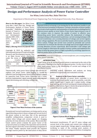
International Journal of Trend in Scientific Research and Development (IJTSRD) Volume 3 Issue 5, August 2019 Available Online: www.ijtsrd.com e-ISSN: 2456 – 6470 Design and Performance Analysis of Power Factor Controller Soe Winn, Lwin Lwin Mar, Hnin Thiri Soe Department of Electrical Power Engineering, Pyay Technological University, Pyay, Myanmar How to cite this paper: Soe Winn | Lwin Lwin Mar | Hnin Thiri Soe "Design and Performance Analysis of Power Factor Controller" Published in International Journal of Trend in Scientific Research and Development (ijtsrd), ISSN: 2456- 6470, Volume-3 | Issue-5, August 2019, pp.2058- 2061, https://doi.org/10.31142/ijtsrd27821 Copyright © 2019 by author(s) and International Journal of Trend in Scientific Research and Development Journal. This is an Open Access article distributed under the terms of the Creative Commons Attribution License (CC (http://creativecommons.org/licenses/by /4.0) Theorectically, unity power factor voltage and current are inphase, low power factor called lagging, is caused by inductive load and high power factor called leading is caused by capacitive load. Power factor Controller has 4 mian portions implemented, signal sensing, signal analysing and signal determining and switching configuring. ABSTRACT Demand of electrical energy is increasing day by day and power quality is one of the buzzword nowadays in Myanmar. Customer awareness of power quality, elecctronics load sensitivity and automation of industrials are pushing hard to improve power quality as never before. Power factor improvement is one of the common ways to improve the quality of power in effective way. Researching power factor controller enhance the deployment of voltage sensing technique with potential transformer, current sensing technique with current transformer, zero crossing detection of voltage and current signals, zener voltage regulation, PIC microcontroller based control system and relay driver system. Voltage and current were sensed by potential and current transformers to evaluate the deviation of voltage and current singals with zero crossing detection circuits respectively. Microcontroller is fed voltage and current singals to determine the quality of power system and implement the relays to keep the power factor as high as possible by switching capacitors to improve power factor of the system. KEYWORDS: potential transformer, current transformer, zero crossing detector, power factor controller I. INTRODUCTION Power factor of an AC electrical power system is expressed as the ratio of the real power, P flowing to the load to the apparent power, S in the cirucit. On the other hand, power factor is the relationship of current and voltage of AC distribution system. switching system. Simulation and analysis are being performed sequencially and evaluated correctly. II. features of the Power factor controller Hence, main objective of power factor controller is to maintain the power quality as good as possible, controller ability should have 2 inputs and 1 output totally, voltage level sensing, current level sensing and compensating power quality of the system. Figure 2 shows the proposed system to control the power quality of the system. IJTSRD27821 BY 4.0) Figure1 Four Main Portions of the symtem Potential and Current transformers are being used to set up signal detecting section to know voltage and current level of the power system in real time. One of the operational amplifier configurations, comparator circuit, is used to analyze when voltage and current signals are changing polarities for time deviation of the system. Microcontroller based control system evaluate the power factor of the proposed system according to the input data and encode the decision signal to drive the correct switching arrangement of the relays. Finally capacitor bank provide the required shortage reactive power by the instruction of relay driver Figure2 System Block Diagram of Power Factor Controller Instrument transformers, PT and CT sense voltage and current level of the system and convert into voltage and current signal respectively. Voltage signal is controlled by rectifying as input of the crossing point analysis of comparator, as current crossing point dection. Crossing time @ IJTSRD | Unique Paper ID – IJTSRD27821 | Volume – 3 | Issue – 5 | July - August 2019 Page 2058
International Journal of Trend in Scientific Research and Development (IJTSRD) @ www.ijtsrd.com eISSN: 2456-6470 signals are being fed controller for power factor determination algorithm of microcontroller after noise cancellation by filters. Control algorithm of microcontroller evaluates the value of power factor by supported voltage and current signals, and displayed out at the monitor, LCD display. On the other hand, control algorithm supports the decision to realy driver to control the relay switchings properly for improvement of reactive power as power quality enhancement. Comparator, LCD, microcontroller, driver and realys work in DC power and DC power supply system is not being calculated in detail. Overall system have implemented and simulated the result of the output and controlled to be acceptable reliability. Portion by portion implementations are shown sequencially. III. Control system configuration A.Voltage and Current Signal Sensing Proposed system deploy potential transformer getting voltage signal from the power system. Potential transformer (PT), also called instrument transformer, is being used in power systems to step down primary votages to lower secondary potential output voltage level. Transformer can be easily measured by the ordinary low voltage instrument like a voltmeter, wattmeter and energy meters. Potential transformers are connected across or parallel to the line. This special type of transformer allows a meter to take readings from electrical service connections with a higher voltage rating than the meter is normally capable of handling without at potential transformer. reduce high voltage currents to a much lower value and provide a convenient way of safely monitoring the actual electrical current flowing in an AC transmission line using a standard ammeter. Figure4 Current Signal Sensing Configuration Due to different type of arrangement, the current transformer is often referred to as a “series transformer” as the primary winding, which never has more than a very few turns, is in series with the current carrying conductor supplying a load. Figure 4 shows current signal sensing configuration for power factor evaluation. Designing of proposed system is being favored rather than component value calculation. B.Analysis of Power Factor Signal Signals from PT and CT were being fed to zero crossing detectors circuit to analyse the time when the voltage and current cross the axes. Voltage signal was half wave rectified by diode and support to the non inverting terminal of the op amp comparator circuit to provide time interrup singal for controller by regulating with zener. Figure3 Voltage Sensing Configuration The primary terminals can be connected either in line-to-line or in line-to-neutral configuration of voltages ratio. Essentially, three various types, an electromagnetic type, a capacitor type, and an optical type. Optical potential transformers are used in optical equipment applications to measure resistance and reactances. The capacitor type of is typically utilized for higher voltages, whereas the electromagnetic device is a wire-round type of transformer. Typically, potential transformers combine both burden and accuracy, because they are normally dependent on each other. Most potential transformers have smaller cores and windings, compared to regular power transformers. Figure 3 shows voltage sensing configuration of the proposed system to support for zero crossing detection for power factor evaluation. Two winding transformer is used as potential transformer and configuration above will evaluate the required voltage information of the system. Current Transformer(CT) is also type of instrument transformer, that is designed to produce an alternating current in its secondary winding which is proportional to the current being measured in its primary. Current transformers Figure5 Analyzing of Power Factor Signal by Zero Crossing Detector Current signal is directly provide to zero crossing detector and output signal is being regulated by zener. Ready to proceed current signal provide to controller altogether with voltage signal for accurate power factor analysis. Signals for PT and CT are also directly provide for timing by filtering RC filter for voltage and C filter for current respectively. C.Power Factor Determination by Microcontroller Signals from PT and CT are provided to pin 2 and 3 of PIC microcontroller 18F4550 which is mid range processor as in figure 6. @ IJTSRD | Unique Paper ID – IJTSRD27821 | Volume – 3 | Issue – 5 | July - August 2019 Page 2059
International Journal of Trend in Scientific Research and Development (IJTSRD) @ www.ijtsrd.com eISSN: 2456-6470 Figure8 Power Factor Measurements The simulation result of the proposed system is pretty accurate and algorithm drives the system in good manner in no load condition. Overall power factor controller with improvement and load condition simulation is also satisfied and the results are acceptable. Complete system set up with load condition is as the following figure. Figure 6 Microcontroller for Power Factor Determination Zero crossing signals are also provided to controller, voltage signals to pin 33 and current signals to pin 34. Pin 35 to Pin 40 are connected with 20x4 LCD display for power factor monitoring. Pin 21, 22, 29 and 30 are connected to relay driver IC ULN2003A. Figure 7 show the algorithm of power factor evaluation and correction of the proposed system. Figure9 Complete Power Factor Controller Circuit with Load Power factor controller with working proposed system is described. Ordinary 350W transformer was used as potential transformer and so as 100:5 current transformers respectively. LM358, dual OP amp IC, was used as comparator with good accuracy. 5.1V zeners were using as regulator to stablized the signals. 12V relays were using as switching devices and resistive load is 100W blub, water pump mother as inductive load. IV. Simulation and result evaluation Proposed system use 1KΩ and 10KΩ resistor as zero crossing dectector gain controller, OP amp voltage comparator.gain 10. Filter capacitor is calculated as 17uF. Powr factor is calculating as - Time difference = average value of timer/1000. Figure7 Algorithm of the PIC Microcontroller Algoritm start configuraing LCD Display. Signals and data are decleared for implementation. Voltage and current signal are waiting and counter is started once first voltage and current signals are detected. Second zero crossing signals are also waiting and calculate power factor once detected. D.Power Factor Improvement The following figure shows input waveform of voltage and current with phase difference. Both of the signals are fed to zero crossing detectors, which give square waves in digital format. These digital waveforms are used by microcontroller to calculate power factor. Microcontroller takes decision to switch appropriate capacitors to compensate for power factor. Figure 10 Experimental Setup of Power Factor Controller @ IJTSRD | Unique Paper ID – IJTSRD27821 | Volume – 3 | Issue – 5 | July - August 2019 Page 2060
International Journal of Trend in Scientific Research and Development (IJTSRD) @ www.ijtsrd.com eISSN: 2456-6470 V. Efficiency of DC power supply is acceptable enough to drive the controller and to supply zero crossing detectors. Zener regualtion and capacitor filter circuits are also working in goog manner. PIC microcontroller input output and timing are all seamlessly set up. In the system relay drivers work well but no security and safety for relay driver and capacitors switching. VI. CONCLUSION Power factor controller is good for using witch capacitor bank where several inductive load utilizing places, as inducstrial and enterprise. Acknowledgment Author would like to acknowledge, Minister of Education, Rector of Pyay Technological University, faculties of Department of Electrical Power Engineering, colleagues from Power Electronics and Device Control Engineering Division, Parents, especially dedicated to my wife and son. References [1]Zin Mar Soe, Mar.2017. Design and Implementation of Static Frequency Converter for Aircraft Power System, ME Thesis, Mandalay Technological University. Discussion and evaluation Management Research (IJETMR), Volume 5, Issue 2 , February 2018. [3][17Sai] PATILKHEDE2, SANKET PATIL3,ABHISHEK YADAV4, “Automatic Power Factor Microcontroller” International Journal of Engineering Technology Science and Research (IJETSR), Volume 4, Issue 4,April 2017. SAIRAJ GHARAT1, DARSHANA Correction Using [4][16Bho] “Reactive Power Compensation in 132kV&33kV Grid of Narsinghpur Area”, Computation Engineering Research (IJCER), Volume 6, Issue 6, June 2016. Prof. J. C Bhola, Prof. Pragti Jyotishi, International Journal of [5][15Ano] PIC www.alldatasheet.com/PIC, 2015. Anonymous, Datasheet and Guide Book of 18F4550 Microcontroller, [6][14Ana] Sharma, Mr.Vijay Kumar Sharma “Power Factor Correction Using Capacitive Bank ”,Int. Journal of Engineering Research and Applications ISSN : 2248- 9622, Vol. 4, Issue 2(Version 1), pp.393-395, February 2014. Mr.Anant Kumar Tiwari, Mrs. Durga [7][13Akw] “Concepts of Reactive power Control and Voltage Stability Methods in Power System Network”, Journal of Computer Engineering (IOSR-JCE) Volume 11, Issue 2,(May-Jun 2013). Akwukwaegbu I. O, Okwe Gerald Ibe, [2][18Ara] Power Factor Correction for Industry Application” International Journal of Engineering Technology and Ararso, “Design and Simulation of Automatic @ IJTSRD | Unique Paper ID – IJTSRD27821 | Volume – 3 | Issue – 5 | July - August 2019 Page 2061