Download
1 / 4
40 likes | 57 Vues
Wear occurs to the hardest of materials, including diamond, wear studies having focused on surface damage in terms of material removal mechanisms, including transfer film, plastic deformation, brittle fracture and tribochemistry Within most industry segments, significant financial losses may be incurred due to accelerated wear of various components. In order to minimize the effects of mechanical wear and extend product life, coating solutions introduced into production and is further developing them to meet even more demanding wear applications. Applying coatings is an established industrial method for resurfacing metal parts. Failure of mechanical components due to wear is the most common and unavoidable problem in mechanical processing industries. This paper explore various techniques of assessing the wear resistance of coated and uncoated materials. Test equipment for sliding wear, erosion, impact and dynamic wear tests is induced, Processes for measuring wear rates are highlighted and Procedure for measuring wear of a specimen is discussed. Mechanical devices sometimes fail because of the wear in the moving parts due to friction. This results in significant amount of investment to replace the worn out parts. The wear testing rig is a device to simulate wears in the laboratory. The present work is about a design and manufacturing process of a pin on disk apparatus which is used as a test method for determining the wear of any two sliding materials. The aim of this paper is to give information about the design steps and manufacturing procedure for the pin on disk apparatus and to discuss the problems follows the design and manufacturing process. Km Sneha Soni | Abhishek Kumar | Adarsh Kumar Srivastav | Krishnanad Yadav | Mr. Rakesh Kumar Yadav "Fabrication of Pin-on-Disc Wear Test Rig" Published in International Journal of Trend in Scientific Research and Development (ijtsrd), ISSN: 2456-6470, Volume-4 | Issue-4 , June 2020, URL: https://www.ijtsrd.com/papers/ijtsrd30917.pdf Paper Url :https://www.ijtsrd.com/engineering/mechanical-engineering/30917/fabrication-of-pinondisc-wear-test-rig/km-sneha-soni<br>

E N D
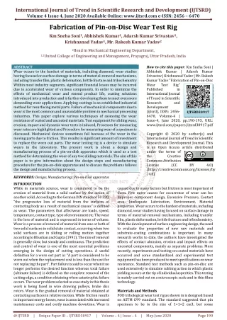
International Journal of Trend in Scientific Research and Development (IJTSRD) Volume 4 Issue 4, June 2020 Available Online: www.ijtsrd.com e-ISSN: 2456 – 6470 Fabrication of Pin-on-Disc Wear Test Rig Km Sneha Soni1, Abhishek Kumar1, Adarsh Kumar Srivastav1, Krishnanad Yadav1, Mr. Rakesh Kumar Yadav2 2Head in Mechanical Engineering Department, 1,2United College of Engineering and Managament, Prayagraj, Uttar Pradesh, India ABSTRACT Wear occurs to the hardest of materials, including diamond, wear studies having focused on surface damage in terms of material-removal mechanisms, including transfer film, plastic deformation, brittle fracture and tribochemistry Within most industry segments, significant financial losses may be incurred due to accelerated wear of various components. In order to minimize the effects of mechanical wear and extend product life, coating solutions introduced into production and is further developing them to meet even more demanding wear applications. Applying coatings is an established industrial method for resurfacing metal parts. Failure of mechanical components due to wear is the most common and unavoidable problem in mechanical processing industries. This paper explore various techniques of assessing the wear resistance of coated and uncoated materials. Test equipment for sliding wear, erosion, impact and dynamic wear tests is induced, Processes for measuring wear rates are highlighted and Procedure for measuring wear of a specimen is discussed. Mechanical devices sometimes fail because of the wear in the moving parts due to friction. This results in significant amount of investment to replace the worn out parts. The wear testing rig is a device to simulate wears in the laboratory. The present work is about a design and manufacturing process of a pin-on-disk apparatus which is used as a test method for determining the wear of any two sliding materials. The aim of this paper is to give information about the design steps and manufacturing procedure for the pin-on-disk apparatus and to discuss the problems follows the design and manufacturing process. KEYWORDS: Design; Manufacturing; Pin-on-Disk apparatus INTRODUCTION While in materials science, wear is considered to be the erosion of material from a solid surface by the action of another solid. According to the German DIN standard 50 320, “the progressive loss of material from the surfaces of contacting body as a result of mechanical causes” is defined as wear. The parameters that affectwear are loads, speed, temperature, contact type, type of environment etc. The wear is the loss of material and is expressed in terms of volume. Wear is a process of removal of material from one or both of two solid surfaces in solid state contact, occurring when two solid surfaces are in sliding or rolling motion together according to Bhushan and Gupta (1991). The rate of removal is generally slow, but steady and continuous. The prediction and control of wear is one of the most essential problems emerging in the design of cutting operations. A useful definition for a worn out part is: “A part is considered to be worn out when the replacement cost is less than the cost for not replacing the part”. Part failure is said to occur when it no longer performs the desired function whereas total failure (ultimate failure) is defined as the complete removal of the cutting edge, a condition obtaining when catastrophic failure occurs. The wear problem selected as case study in this thesis work is being faced in wire drawing pulleys, brake disc rotors. Wear is the gradual removal of material obtained at contacting surfaces in relative motion. While friction results in important energy losses, wear is associated with increased maintenance costs and costly machine downtime. Wear is How to cite this paper: Km Sneha Soni | Abhishek Kumar | Adarsh Kumar Srivastav | Krishnanad Yadav | Mr. Rakesh Kumar Yadav "Fabrication of Pin-on-Disc Wear Test Rig" Published in International Journal of Trend in Scientific Research and Development (ijtsrd), ISSN: 2456- 6470, Volume-4 | Issue-4, June 2020, pp.190-193, URL: www.ijtsrd.com/papers/ijtsrd30917.pdf Copyright © 2020 by author(s) and International Journal of Trend in Scientific Research and Development Journal. This is an Open Access article distributed under the terms of the Creative Commons Attribution License (CC (http://creativecommons.org/licenses/by /4.0) IJTSRD30917 BY 4.0) caused due to many factors but friction is most important of them. Few more causes for occurrence of wear can be: Improper component design, Excessive Pressure, Contact area, Inadequate Lubrication, Environment, Material properties. Wear occurs to the hardest of materials, including diamond, wear studies having focused on surface damage in terms of material-removal mechanisms, including transfer film, plastic deformation, brittle fracture and tribochemistry. With the development of surface engineering design, the need to evaluate the properties of new raw materials and substrate-coating combinations is important. In many research works to date, the authors have investigated the effects of contact abrasion, erosion and impact effects on uncoated components, mainly as separate problems. More recently, experiments and testing on coated materials have occurred and some standardized and experimental test equipment has been produced to meet specifications on wear resistance. Standard test methods such as pin-on-disc are used extensively to simulate rubbing action in which plastic yielding occurs at the tip of individual asperities. This testing is mainly carried out on a microscopic scale and in thin films technology. Materials and Methods POD tribological wear test rig as shown in is designed based on ASTM G99 standard. The standard suggested that pin specimen to be in the size of 1×1×2 cm3, but some @ IJTSRD | Unique Paper ID – IJTSRD30917 | Volume – 4 | Issue – 4 | May-June 2020 Page 190
International Journal of Trend in Scientific Research and Development (IJTSRD) @ www.ijtsrd.com eISSN: 2456-6470 researchers use different dimensions based on the application of their study. The size of the pin specimen may vary from 2 mm to 10 mm in diameter, and disc specimen from 30 to 100 mm in diameter with a thickness of 2 to 10 mm. POD test is one of the most common test in tribology study, and it consists of several important parts. The setup incorporates a linearly imposed pin specimen of a specified material by method of applying weights normal to the pin to push the pin specimen to a rotating disc specimen of a specified materials powered by an AC motor or a DC servo motor. The setup is mounted such a way that the vibration effects will not affect the test. Another mechanism for applying load is by using pneumatic, hydraulic, or power screw. ASTM G99 suggests that the motor’s speed to be in the range of 60 to 600 rpm. The wear test cycles simulate the distance cut of the two imposed specimens, these test cycles help researchers to know the wear performance of the two materials during the sliding process subjected to a specified velocity, temperature, lubricant, load, pressure, duration, and friction. Wear measurement is carried out to determine the amount of materials removed (or worn away) after a wear test, (and in reality after a part in service for a period of time). The material worn away can be expressed either as weight (mass) loss, volume loss, or linear dimension change depending on the purpose of the test, the type of wear, the geometry and size of the test specimens, and sometimes on the availability of a measurement facility. Common techniques of wear measurement include using a precision balance to measure the weight (mass) loss, profiling surfaces, or using a microscope to measure the wear depth or cross- sectional area of a wear track so as to determine the wear volume loss or linear dimensional change. Pin on disc figure. Mass loss Mass loss measurement by a precision balance is a convenient method for wear measurement, especially when the worn surface is irregular and unsymmetrical inshape. Sample to be measured is carefully cleaned, and the weight is measured before and after a wear test. The difference in weight before and after test represents the weight loss caused by wear. The unit can be gram (g) or milligram (µg). Volume Loss Wear volume is normally calculated from the wear track (scar) depth, length, width and/or scar profile according to the geometry of the wear track/scar. A surface profilometer or a microscope with scale is used for the measurement. The reporting unit of wear volume loss is mmᶾ or µmᶾ. Wear volume loss enables a better comparison of wear among materials having different densities. However, it is not easy to measure volume loss when a wear track is irregular. In this case, mass loss may be measured first, and the volume loss is calculated if the materials is uniform and its density is known. Linear dimension loss Measuring wear by linear dimension change is very useful in many engineering situations, where certain dimension such as length, thickness or diameter is more critical to the normal function of the system. A surface profilometer or a microscope can be used. The unit for linear dimension loss can be µm or mm. Wear rate Wear rates are calculated results reflecting wear mass loss, volume loss or linear dimension change under unit applied normal force and/or unit sliding distance. Wear rate can be expressed in many different ways. @ IJTSRD | Unique Paper ID – IJTSRD30917 | Volume – 4 | Issue – 4 | May-June 2020 Page 191
International Journal of Trend in Scientific Research and Development (IJTSRD) @ www.ijtsrd.com eISSN: 2456-6470 Mechanism of wear In erosive wear situation, particles that are normally entrained in a fluid can impact the wearing surface. The load between the particle and surface results from the momentum and kinetic energy of the particle. This difference in the loading situation results in a modification of equation used to describe the wear, which can be shown by a simple model for particle impact. In erosion it has been established that the angle at which the stream impinges the surface influences the rate at which material removed from the surface and that this dependency is also influenced by the nature of wearing material. Such a dependency is to be anticipated. This can be seen by considering the impact of a single particle with a surface. This angle determines the relative magnitude of the two velocity components of the impact, namely the component normal to the surface and the one parallel to the surface. The normal component will determine how long the impact will last i.e. the contact time, etc, and the load. The product of tc and the tangential velocity component determine the amount of sliding that takes place. Fabrication In this pin on disc apparatus those components which are installed are listed as ½ horse power motor specifically we had used drilling motor, two sets of dc motors such as car wiper motors, speed controlling regulators to control the speed of all three motors, three jaw chuck for holding the specimen pin, long thread bolts and nuts, disc of material by which specimen is to be weared, frame of light mild steel and other electrical auxiliaries, etc. Motor: This electric motor can replace worn out or broken in electric or automatic drilling machine which has general use in garage. Designed with durable rigid base, this electric motor can reach speeds upto high rpm to power your equipment like new. At ½ HP of power output, this electric motor can give you a boost they need to work at peak efficiency. DC motors: These motors installed in the set up to give the x axis and y axis motion to the specimen post or the pin holder so that we able to change the excess worn diameter on the disc which is fitted by the two bolt nut setup on the welded plate on the shaft of motor. Long thread bolt and nut: The main purpose of these are to rotate with the help of dc motor and provide the specimen holder the x as well as y axis. Speed controlling regulators: These controllers are required to maintain the rpm of the motor so that we can take readings at different speeds. Also required to produce the motion to set the pin position with x and y motion. Photography Conclusion If wear tests are carried out with a high degree of simulation of the service situation, then the results can be used with considerable confidence in selecting the best wear-resistant coating system. Every wear test, whether for bulk material or coatings, can be complicated by equipment problems, test procedures, sample preparation, inconsistency in abrasive materials and the wrong interpretation, of the test information. Thin coatings require greater care in wear tests in order to avoid penetration, which requires lighter loads and shorter test durations. Surface roughness also influences the tribological performance of a mechanical system. It has also been shown for thin, hard coatings that the rougher the surface finish, the lower the coating adhesion, as measured by scratch-testing methods. If significant plastic flow or deformation of materials occurs in wear testing, using weight loss may give different results to using wear volume loss. The benefits of applying surface coatings to reduce wear can be measured in many practical ways such as machine efficiency, reduced power requirements and longer running life. @ IJTSRD | Unique Paper ID – IJTSRD30917 | Volume – 4 | Issue – 4 | May-June 2020 Page 192
International Journal of Trend in Scientific Research and Development (IJTSRD) @ www.ijtsrd.com eISSN: 2456-6470 [4]https://www.researchgate.net/publication/28958822 9_DESIGN_AND_DEVELOPMENT_OF_PIN_DISC_WEAR_ TESTER_PART_5 Acknowledgements The Author sincerely thanks Mr. Rakesh Kumar Yadav, Head of Department in Mechanical Engg. And also to faculty in charge of Workshops, UCEM providing necessary help in conducting experiments. REFERENCES [1]http://emrtk.uni- miskolc.hu/projektek/adveng/home/kurzus/korsz_an yagtech/1_konzultacio_elemei/wear_testing_measure ment.htm [5]https://www.youtube.com/watch?v=t9RqMKsdoo8 [6]https://www.youtube.com/watch?v=5h5Y8VChtI4 [7]Materials Science and Engineering Book by David G. Rethwisch and William Callister. [8]https://www.tribonet.org/tribology-and-contact- mechanics-books/ [2]https://www.element.com/more-sectors/medical- device/pin-on-disk-wear-testing [9]Engineering Tribology Book by A. W Batchelor and G. W. Stachowiak [3]https://www.researchgate.net/publication/33008961 7_A_Review_on_Tribological_Wear_Test_Rigs_for_Vario us_Applications [10]https://en.wikipedia.org/wiki/Wear [11]Williams, J. A. (2005). "Wear and wear particles - Some fundamentals." Tribology International 38(10): 863- 870 @ IJTSRD | Unique Paper ID – IJTSRD30917 | Volume – 4 | Issue – 4 | May-June 2020 Page 193