Download

1 / 4
40 likes | 52 Vues
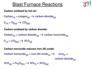
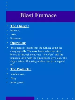
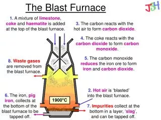
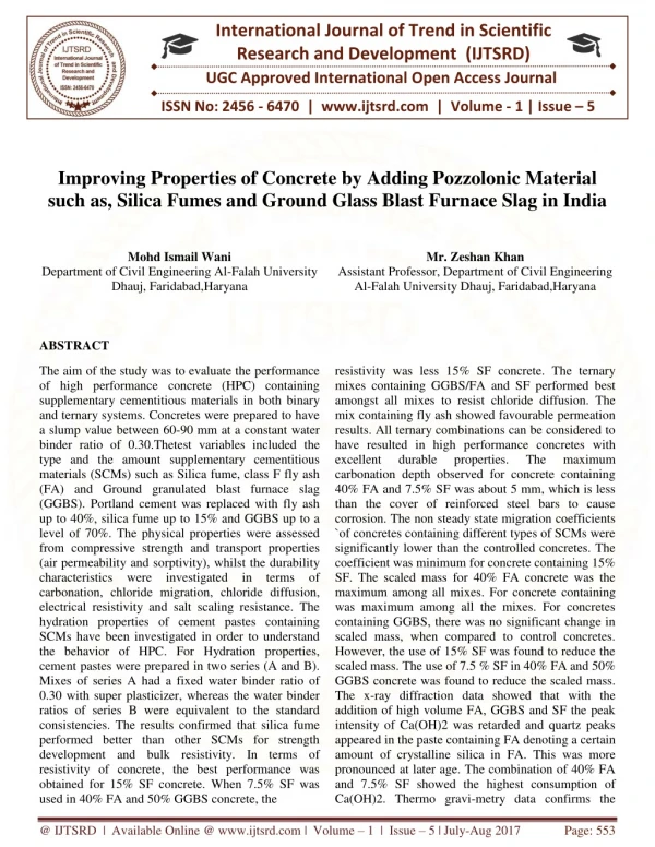
The Black Cotton soils occurs mostly in the central and western parts and covers approximately 20 of the total area of India. Because of its high swelling and shrinkage characteristic, The Black Cotton soil have been a challenge to the highway engineers. The Black Cotton soil is very hard when dry, but loses strength completely when in wet condition. It is observed that on drying, The Black Cotton soil develops cracks at varying depth, It is a well known fact that water is the worst enemy of road pavement, perticularly inexpensive soil areas cause of road failure that water has got easy access into the pavement. A Literature review has been presented that has given me the somewhat direction and point of investigation in the different correlation methods of soil properties. It has also given the effect of various soil properties on CBR value. Experimental Work shows the different types of experiments to be performed to evaluate various soil properties. These properties are Grain Size Analysis, Liquid Limit, Plastic Limit, Plasticity Index, Shrinkage Limit, Maximum Dry Density, Optimum Moisture Content, CBR value. It also shows the summary report of results of various experiment performed on the number of soil sample. Now we are added some material that improve the soil strength so we can used in road pavement consruction. we added GGBS Ground Granulated Blast Furnace Slag material to stabilize the black cotton soil we are added suitable proportion of GGBS material in the soil proportion are 3 ,6 ,9 and 12 and to check at what proportion we get best result. So we started performing test and analysis the result. GGBS Ground Granulated Blast Furnace Slag has usually used as stabilizer for developing the engineering properties of soil. GGBS is a byproduct generaed during manufacturing of iron and steel. The GGBS is environmental and ecofriendly by product. GGBS improve the engineering properties and stabilized the soil. It also reduce the cost of pavement. Vedwala Khushbu M | Priyank H. Patel | Vishal N. Patel "Stabilization of Black Cotton Soil using GGBS (Ground Granulated Blast Furnace and Slag)" Published in International Journal of Trend in Scientific Research and Development (ijtsrd), ISSN: 2456-6470, Volume-4 | Issue-4 , June 2020, URL: https://www.ijtsrd.com/papers/ijtsrd31556.pdf Paper Url :https://www.ijtsrd.com/engineering/civil-engineering/31556/stabilization-of-black-cotton-soil-using-ggbs-ground-granulated-blast-furnace-and-slag/vedwala-khushbu-m

E N D
International Journal of Trend in Scientific Research and Development (IJTSRD) Volume 4 Issue 4, June 2020 Available Online: www.ijtsrd.com e-ISSN: 2456 – 6470 Regenerative Braking and Controlling of Hybrid Energy Storage System for an e-Vehicle Mr. Niliket Deshmukh, Mr. Shreejit Thorat, Mr. Vishvanath Javanjal, Ms. Nikita Chandurkar, Ms. Roshani Borakhade, Ms. Radhika Agnihotri Department of Electrical Engineering, Shri Sant Gajanan Maharaj College of Engineering, Shegaon, Maharashtra, India ABSTRACT Electrical vehicle with its high efficiency, noiseless operation and effective elimination of toxic exhaust gases have gained attention this decade. In earlier times, when conventional vehicles were used a large amount of energy was wasted due to the friction between the wheels and brake pads. In regenerative braking instead of wasting the energy produced during braking, the excess energy is stored and reused with the help of ultra-capacitor based arrangement. Hence regenerative braking plays a vital role in electric vehicles. The motor is used as a generator to charge the vehicle's battery. However, the regenerated energy is not fully returned to the battery. Regenerative braking refers to a system in which the kinetic energy of the vehicle is stored temporarily, as an accumulative energy, during deceleration, and is reused as kinetic energy during acceleration it has an energy storage system comprise of the ultra-capacitor module and a lead Acid battery connected through a PWM Controller to a PMDC motor. These kinds of brakes allow batteries to be used for longer periods of time without the need to be plugged into an external charger. This allows efficient, high power transfer under regenerative braking and acceleration. The ultra-capacitor voltage is a key control parameter that affects the efficiency of the overall system. KEYWORDS: introduction, block diagram, construction, working, expt. model, results, conclusion How to cite this paper: Mr. Niliket Deshmukh | Mr. Shreejit Thorat | Mr. Vishvanath Javanjal Chandurkar | Ms. Roshani Borakhade | Ms. Radhika Agnihotri "Regenerative Braking and Controlling of Hybrid Energy Storage System for an e- Vehicle" Published in International Journal of Trend in Scientific Research and Development (ijtsrd), ISSN: 2456-6470, Volume-4 | Issue-4, June 2020, pp.1463-1466, www.ijtsrd.com/papers/ijtsrd31567.pdf Copyright © 2020 by author(s) and International Journal of Trend in Scientific Research and Development Journal. This is an Open Access article distributed under the terms of the Creative Commons Attribution License (CC (http://creativecommons.org/licenses/by /4.0) | Ms. Nikita IJTSRD31567 URL: BY 4.0) INTRODUCTION: Regenerative braking utilizes the kinetic energy generated by the motor during a brake process. Regenerative brake is an energy recovery mechanism which slows a vehicle by converting its kinetic energy into another form, which can be either used immediately or stored until needed. Thus, the generated electricity during the braking is fed back into the supply system, whereas in battery electric vehicles, the energy is stored in a battery. The presented RBS is composed of a ultra-capacitor module 500 fard,3v 6cells in series, Lead acid battery pack 12 v,7.2 amp hour, PWM Controller 80 watt and 2A IN5822 diode and 12v ,10 watt RS725 Pemanent magnetr DC motor. Super capacitors on the other hand remain the only viable alternative for a powerful yet dynamic auxiliary source which is able to compliment the already stable main energy source. In the above energy management system battery is associated with high power component like super capacitor. It is one of crucial task to improve both efficiency and performance of electric vehicle regarding electric power density and energy capacity. A.Block Diagram Usually when two or more energy sources are involved in a hybrid energy storage system for an electric vehicle, these sources can be distinguished by their energy storage and power delivery capacities respectively. Due to today’s requirement of maximum regenerative braking energy recapture, power batteries being a chemical energy conversion process are not as dynamic enough for this purpose. In our project we are implementing battery-UC hybrid technique. Lead acid battery act as a primary source for the system. Pulse width modulation controller is key element for variation of speed of motor. By adjusting the position, we can operate for motoring and braking mode. Use of pulse width modulator to control speed of motor has adv advantage in that power loss in switching transistor is small because the transistor is either fully on or fully off. An electric machine is a key component of a hybrid energy system. It performs electromechanical interconversion in the course of charge and discharge. When it operates in charge mode, it works as a motor to accelerate the flywheel for converting electricity into mechanical energy. During the operation of discharge mode, it works as a generator to decelerate the flywheel for converting mechanical energy into electricity. Super capacitors also known as Electric Double Layer Capacitors (EDLCs) or ultra capacitors, have a high energy density when compared to conventional capacitors, typically thousands of times greater than a high capacitance electrolytic capacitor. In this project the ultra @ IJTSRD | Unique Paper ID – IJTSRD31567 | Volume – 4 | Issue – 4 | May-June 2020 Page 1463
International Journal of Trend in Scientific Research and Development (IJTSRD) @ www.ijtsrd.com eISSN: 2456-6470 capacitor act as auxiliary source in the system. Super capacitor captures the energy whatever it is wasted during regenerative braking. CONSTANT SPEED: In this mode of operation, to get the constant rated speed of motor, we gradually increase the speed of the motor by increasing the terminal voltage of motor by PWM controller. And hence, the rated speed of motor can be achieved and motor rotates with constant speed. In this mode, the terminal voltage of the motor is maintained constant at 12 v however, the armature current must maintain its direction. DEACCELEARTION AND BRAKING MODE: In this mode of operation, as soon as the DPDT switch is shifted to braking mode, the motor slows down and starts acting as a genearator and back emf of motor, battery voltage gets reduced. At the same time, the energy which get produced during braking is get absorbed by the Super capacitor, which is fed through the alternate unidirectional circuit. And Hence, the Regenerative Braking takes place. While during Braking, the energy absorbed by the Super capacitor depends on the energy produced by motor during braking, speed at which braking takes place, and moment of inertia of motor. And therefore, the voltage of Super capacitor increases above 12 volt and it gets charged. The diode is used in braking circuit to avoid reverse current flow while Motoring. C.Principle and Methodology Regenerative braking is an energy recovery mechanism that slows down a moving vehicle or object by converting its kinetic energy into a form that can be either used immediately or stored until needed. In this mechanism, the electric traction motor uses the vehicle's momentum to recover energy that would otherwise be lost to the brake discs as heat. This contrasts with conventional braking systems, where the excess kinetic energy is converted to unwanted and wasted heat due to friction in the brakes, or with dynamic brakes, where the energy is recovered by using electric motors as generators but is immediately dissipated as heat in resistors. In addition to improving the overall efficiency of the vehicle, regeneration can significantly extend the life of the braking system as the mechanical parts will not wear out very quickly. Electric motors, when used in reverse, function as generators and will then convert mechanical energy into electrical energy. Vehicles propelled by electric motors use them as generators when using regenerative braking, braking by transferring mechanical energy from the wheels to an electrical load. D.Experimental Model and Observations Here are some observations of our project which are considered before and after braking. Before braking: B.Construction Diagram and description Figure Circuit diagram The most basic method of combining a super capacitor with battery pack is a simple way of parallel configuration. In this parallel topology Battery system, PMDC Motor, DPDT switch, DC ammeter, Digital Multimeters, Diodes and small flywheel is used. Explaination in detail Modes of operation and control strategy of an Electrical Drive. An Electrical Drive has different modes of operation, which is given by ?Starting and Acceleration mode; ?Constant speed ?Deceleration or braking mode STARTING AND ACCELERATION MODE: During normal working condition, the DPDT switch is kept in motoring mode. The speed of the dc motor is controlled by armature voltage control method, which is directly proportional to its terminal voltage. Controller will drive the motor and control the power flow. During starting and accelerating, motor will demand more current which will fed through the hybrid source of energy. In this stage the armature current flows through positive terminal of source to negative terminal .Diode is used to avoid the reverse current flow during breaking. Hence during normal driving mode, the power will be delivered by both battery and super capacitor. @ IJTSRD | Unique Paper ID – IJTSRD31567 | Volume – 4 | Issue – 4 | May-June 2020 Page 1464
International Journal of Trend in Scientific Research and Development (IJTSRD) @ www.ijtsrd.com eISSN: 2456-6470 ?At initial condition: The super capacitor is in discharged mode. PWM controller is at minimum position. Switch is kept in motoring mode. Motor is at rest. After Braking: ?At Running Condition: Now we gradually increase the speed of motor by using PWM Controller up to rated speed. Following are the observations before braking: Terminal Voltage (Vt) = 12.09 V Motor Current (Ia) = 0.74 A Capacitor Voltage (Vc) = 2.60 V At Braking Condition: Switch is changed to braking mode. Due to regenerative braking, the wasted energy gets stored in the super capacitor. Following are the observations after braking; Terminal Voltage (Vt) = decreases from 4 to 0 Motor Current (Ia) = decreases from 2.8 to 0 Capacitor Voltage (Vc) = 2.66 E.Numerical Equations As per observations initially self discharge test of super capacitor was tested. The module of super capacitor was firstly charged by the constant dc power supply and was tested under constant current rates, where the change in capacitance was found to be decrease for increased charging rates. Further the testing of super capacitor module under the regenerative braking had been done in main proposed system, in order to justify study analysis regarding super capacitor, we have studied technical terms in detail. Moreover, energy consumed by the super capacitor module for a 20 min interval was calculated. Power Supply Voltage Charging Discharging V0 V1 T sec I V0 V1 T sec 3.7 10 20.5 1 10 3.7 20 Calculations for Ultra Capacitor- 500F, 3V (six cells are connected in series) 1.Ceq = 500/6 = 83.33F 2.Energy stored: E=1 CV2 2 = (1/2)*500*9 = 2250 = 2250/600 = 0.625-watt hr 3.Minimum allowable energy: %d= (Vmin) X 100 (Vmax) =3.7 X 100 =37% 10 4.Ampere hour efficiency: ⋂ = dis current X time of dis Charge current X time of charge = 0.6X20X60 = 58.53% 1X20.5X60 5.Watt hour efficiency: ⋂ = time of disXdis current X dis voltage time of charge X charging current X charging voltage = 20X60X0.6 (3.7) = 21.6% 20.5X60X1 (10) = 0.6X20X60 = 58.53% Watt hour efficiency Ampere hour efficiency I 12 21.65% 58.53% 0.7 RESULT: 1X20.5X60As per observations initially self discharge test of super capacitor was tested. Likewise, the charging current and discharging current was monitored and effective value was calculated. Moreover, energy consumed by the super capacitor module for a 20 min interval was calculated The ampere-hour and watt-hour efficiency of super capacitor was also calculated and found to be 58.53% and 21.65%. In the topology of the given hardware implemented system, it is observed that motor stops running within a time, based on super capacitor charging fundamentals of the proposed hybrid energy storage system were explained in detail especially in two different operating modes .DPDT switch was used to change the operating modes and finally the braking current and braking time were noted. In this, motor initially powered by the battery to operate drive system in driving mode. As soon as switching takes place for braking mode which will further allow the controller to operate motor for regenerative braking. From this it is observed that super capacitor gives the better performance for electric vehicle and its implementation in regenerative braking will certainly be used to improve energy recovery from the system. The control of vehicle speed during all modes of operation (motoring, constant speed and braking) should be maintained for the proper EV operation. In this way, we can capture up to 8-25% of the energy otherwise wasted during braking. current .The operating @ IJTSRD | Unique Paper ID – IJTSRD31567 | Volume – 4 | Issue – 4 | May-June 2020 Page 1465
International Journal of Trend in Scientific Research and Development (IJTSRD) @ www.ijtsrd.com eISSN: 2456-6470 F.CONCLUSION: In this paper, regenerative braking for hybrid energy storage system for electric vehicle is mainly focused and hence the given prototype is developed. Regenerative braking system were experimentally verified in the laboratory. Final reading on dc motor had been taken on the given proposed system. Motor is tested on both motoring mode as well as braking mode. Finally, it is observed that energy produced during braking operation in motor is get stored in super capacitor successfully. Additionally, the stored energy is reused during the acceleration or high current demand of the motor. The calculations regarding thesis analysis were studied and calculated successfully. In this way by implementing technology of super capacitor in hybrid energy storage system especially in regenerative braking gives better performances and ultimately reduce stress over the battery and improve its life. Further the efficiency of overall system is dependent on braking rate and initial super capacitor state of charge (SOC). The highest regenerative braking power that super capacitor can capture is likely to occur when the super capacitor SOC is at its lowest level. Acknowledgment (Heading 5) We first pray to our divine source of inspiration “Shri Sant Gajanan Maharaj” whose blessings are always with us. We express our deep gratitude to our Respected Director Mr. Shrikantdada Patil for his kind blessings encouragement and providing us such a good opportunity. No words could be good enough to express our deep gratitude to our respected Principal Dr. S. B. Somani for his kind blessings, inspiration and providing us the necessary support. We feel great pleasure in expressing our deepest sense of gratitude and sincere thanks for valuable guidance, extreme assistance and cooperation extended to us by our Internal Guide Dr. S. R. Paraskar and our co-Guide Prof. A. K. Damral sir in preceding the completion of the dissertation. We are equally indebted to Dr. S. R. Paraskar (Head of Electrical department) for extending necessary help, providing facilities and time-to-time valuable guidance. We are especially thankful to Prof. P. R. Bharambe, Prof. R. S. Kankale, Prof. S. S. Jadhao & Prof Pratik Dhabe for their valuable suggestions and inspiration time to time. This acknowledgement would be incomplete without expressing our special thanks to Prof. U. A. Jawadekar and Dr. Mrs. A. U. Jawadekar for their support during the work. Last but not least, we would like to thanks all the teaching, non-teaching staff members of the Electrical Engineering Department, our family members and colleagues those who helped us directly or indirectly for completing this task successfully. REFERENCES [1]J. Clerk Maxwell, A Treatise on Electricity and Magnetism, 3rd ed., vol. 2. Oxford: Clarendon, 1892, pp.68-73. A Comprehensive Study of Key Electric Vehicle (EV) Components, Technologies, Challenges, Impacts, and Future Direction of Development Fuad Un-Noor 2. Sanjeevikumar Padmanaban 3. Lucian Mihet-Popa 4. Mohammad Nurunnabi Mollah and 5. Eklas Hossaian. Academic Editor: Sergio Saponara Received: 8 May 2017; Accepted: 21 July 2017; Published: 17 August 2017 [2]Ultra capacitors: why, how, and where is the technology. Andrew Burke. Institute of Transportation Studies, University of California-Davis, Davis, CA 95616, USA [3]Simulation and Analysis of Performance of a Pure Electric Vehicle with a Super-capacitor Jinrui N', Zhifu W', Qinglian R2 'School of mechanical and vehicular engineering, Beijing Institute of Technology, Beijing, Chin [4]Regenerative braking of an electric vehicle using ultra capacitors and a Buck-Boost Converter Juan W. Dixon, Micah Ortúzar and Eduardo Wiechmann* Department of Electrical Engineering Catholic University of Chile Casilla 306, Correo 22 Santiago, Chile [5]R. Nicole O. Hegazy, J. Van-Mierlo, and P. Lataire, ‘‘Analysis, modeling, and implementation of a multidevice interleaved DC/DC converter for fuel cell hybrid electric vehicles,’’ IEEE Trans. Power Electron., vol. 27, no. 11, pp. 4445-4458, Jan. 2012 [6]X. Jiaqun and C. Haotian, "Regenerative brake of brushless DC motor for light electric vehicle," Electrical Machines and Systems International Conference on, Pattaya, 2015, pp. 1423- 1428. doi: 10.1109/ICEMS.2015.7385262 (ICEMS), 2015 18th @ IJTSRD | Unique Paper ID – IJTSRD31567 | Volume – 4 | Issue – 4 | May-June 2020 Page 1466