Download
1 / 26
260 likes | 601 Vues
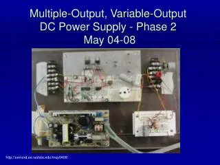
Multiple-Output, Variable-Output DC Power Supply - Phase 2 May 04-08. http://seniord.ee.iastate.edu/may0408/. Multiple-Output, Variable-Output DC Power Supply. Client Senior Design Dr. Lamont Prof Patterson Advisors Dr. Potter Dr. Ajjarapu Team Members Benjamin Voetberg, EE

E N D
Multiple-Output, Variable-Output DC Power Supply - Phase 2 May 04-08 http://seniord.ee.iastate.edu/may0408/
Multiple-Output, Variable-Output DC Power Supply • Client • Senior Design • Dr. Lamont • Prof Patterson • Advisors • Dr. Potter • Dr. Ajjarapu • Team Members • Benjamin Voetberg, EE • Fares Karadsheh, EE • Trung Nguyen, EE • Darrell Long, EE Senior Design :: May 04-08
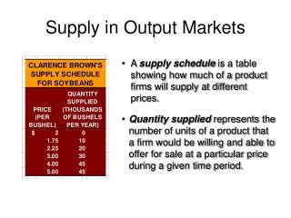
Overview • Project objectives & guidelines • Create low cost dc power supply • Range of voltages • Design Approach • ac to dc • End Result • What the team accomplished • Budget • Price comparison • Layout of cost • Schedule • Project Evaluation • Risk and Risk Management Senior Design :: May 04-08
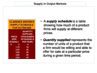
Project Objectives & Guidelines • The project is to design a DC power supply that provides power at various voltages • +/- voltages will include 5V, 6V, 12V, 18V • +/common voltages will include 1.5V, 3.0V, 3.2V, 3.3V, 4.5V, 5V, 6V, 7.5V, 9V, 12V, 15V, 18V, 24V • Voltmeter and Ammeter to display output values • Between 2 to 4 output terminals. Senior Design :: May 04-08
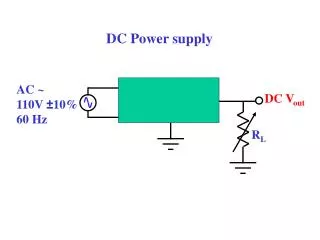
Project Objectives and Guidelines Cont. • Operating Environment • Indoor use for senior design projects • Intended users/uses • Students enrolled in EE/CprE senior design • Possibility for use in freshman and sophomore level labs • Used to test senior design projects that require DC voltage • Assumptions/Limitations • Powered by a 120V, 60Hz wall outlet • +/- 1% ripple output voltage • Function with +/- 5% of wall outlet voltage • Output current not to exceed 1A on each terminal Senior Design :: May 04-08
Design Approach Definitions • PWM : Pulse Width Modulation • Duty Ratio (D) : Time ON divided by the total time • Lm : Magnetizing Inductance of a transformer • For the simulation, 2 choice: • Pspice: Available and have a lot of parts • Electronic Work Bench : Easy and more visual Sample from the simulation Electronic Work Bench was used to simulate the design Senior Design :: May 04-08
Design Approach Buck Converter • Convert ac to dc using bridge rectifier • Buck converter is used to vary the voltage to get desired voltage output • Buck converter output Vo=Vs*D Simple ac/dc conversion Buck converter diagram
Design Approach Flyback Converter • Not able to make 1.5-24 volts directly from 120 V • Use a flyback converter • Flyback converter output equation Vo=Vs(D/(1-D)) N2/N1 Senior Design :: May 04-08
Design Approach PWM • Output equations: Vo=Vs(D/(1-D)) N2/N1 (Flyback) Vo=Vs*D ( Buck ) • PWM : Generate a square wave. (see figure) Trig.source Comparator • The Reason behind using Flyback then a __buck converter is to create an isolation. Senior Design :: May 04-08
Design Approach Taken • A commercial power supply to replace • bridge rectifier • flyback converter. • Power supply eliminates problems • Current and the voltage regulation • Difficulty finding transformer • Saved time • Even with changes still functions as the simulation • Buck converter still used to vary voltage to get desired output Senior Design :: May 04-08
The new design Fixed Buck Converter TL499ACD Variable Outputs 120 VAC Wall outlet 48VDC 25VDC High Freq. Switch Variable Buck Converter Power Supply Senior Design :: May 04-08
End Product Options • Client wants for power supply • Low cost system • Useful to senior design teams • Portable Power Supply Senior Design :: May 04-08
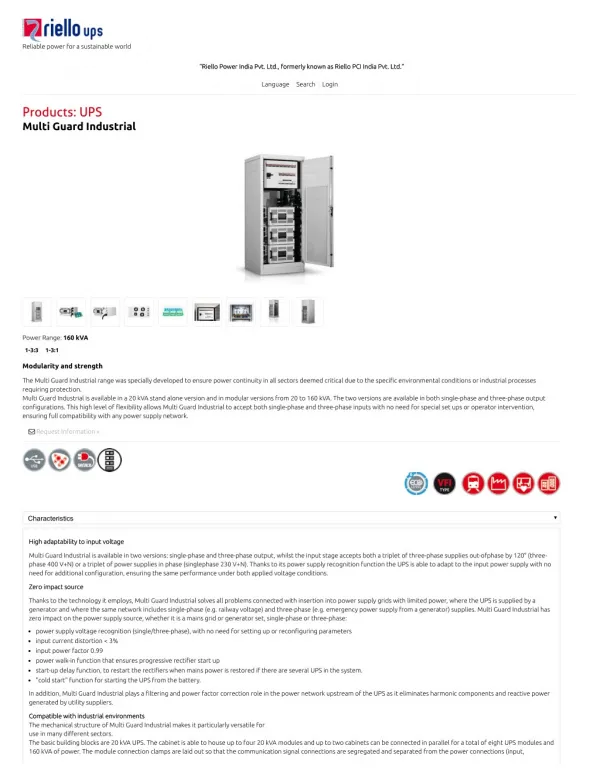
Commercial Power Supply • Astrodyne ® Power Supply • Regulated Output • 85-265 VAC input • Overload Voltage protection • Short Circuit Protection • EMI Filter Senior Design :: May 04-08
Fixed Buck Converter • Switch components • Motorola SG3527A Pulse Width Modulator Control Circuit • Fixed duty ratio, 44 VDC to 25 VDC • Sends square wave to MOSFET DRIVER • Maxim MA4428 Dual High-speed 1.5A MOSFET Driver • Drivers both a N-channel and P-channel MOSFET to achieve the desired switching speed
Texas Instruments TL499A circuitWide-Range Power-Supply Controllers • R1, R2, R3 create a comparison voltage • Voltage varied by changing potentiometer • Minimum output voltage is 2.5 volts. • Maximum output voltage is 24 volts
Digital Display • Maxim ICL7107 3 1/2 Digit A/D Converter • Connected across the output • Displays output voltage to 1/10 accuracy • 2 double digit 7 segment LED displays
Future Work Recommendations • A phase to finalize the project • Necessary future work • Negative voltages • Voltage regulation • Circuit protection • Other future work • Variable current • Voltage zero at start up • Auto zeroing voltmeter Senior Design :: May 04-08
Financial Comparison • Agilent 3631a triple output power supply • 80 watts • + 25 V at 1 A • +6 V at 6 A • $ 1200 • Proam universal ac-dc adaptor • 9 watts • + 1.5, 3, 4.5, 6, 7.5, 9, 12 V at .5 A • $ 9.00 • Our design now • 24 watts • 2.5 to 24 V at 1 A • $ 120 Senior Design :: May 04-08
Personal Time Commitment Senior Design :: May 04-08
First Semester Schedule Senior Design :: May 04-08
Second Semester Schedule Senior Design :: May 04-08
Project Evaluation • Identify possible designs to implement, completed and choose one • Design hardware completed • Hardware specifications completed • Circuit simulations completed • Test hardware almost complete • Documentation completed Senior Design :: May 04-08
Lessons Learned • What went well • Communication • Within the team • With company representatives • Teamwork • What didn’t go well • Unspecific project, time constraint for meeting with clients • Simulation of the circuit • Hardware implementation • Technical knowledge gained • Simulation experienced gained • Power electronics knowledge Senior Design :: May 04-08
Risk and Risk Management • Anticipated risks • Team scheduling • Loss of team member, advisor, or clients • Unanticipated risks • Simulation complications • Hardware implementation • Unable to use certain designs because of cost Senior Design :: May 04-08
Closing Summary • Variable dc output of 2.5 to 24 volts • Meets client specifics • Provides extra voltage values • Digital voltmeter • Accurately provides output voltage • Design is a solid base to further expand • Negative voltages • Circuit protection • Voltage regulation Senior Design :: May 04-08
Questions? Senior Design :: May 04-08