
Smart Battery Equalization and Charging Control Research
Explore a study on equalizing and charging control in smart battery packs, preventing imbalances and enhancing longevity and performance. The research presents simulations, experimental results, and proposed systems for efficient battery management.

Smart Battery Equalization and Charging Control Research
E N D
Presentation Transcript
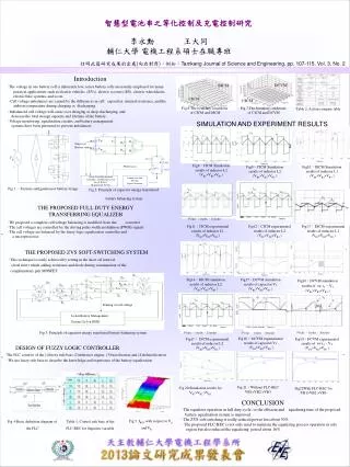
DC1 L1 DS1 VB1 DC3 C1 L3 RG1 RS1 DS3 SC1 VB2 DS2 C2 RS3 L2 RG2 RS2 SC3 DC2 VB1 BC1 C1 Q1 SC2 D1 DS4 Sensor of Battery states RD1 L4 VB3 RS4 DC4 SC4 BC2 VB2 D2 Q2 RD2 Sensing of cell voltage Li-Ion Battery Management System (Li-Ion BMS) SC2 PWM Control SC1 Fuzzy Logic Equalization Controller and Microprocessor based Battery Management System Output state and Driving Signal Generator n-2 n-1 智慧型電池串之等化控制及充電控制研究 李永勳 王大同 輔仁大學 電機工程系碩士在職專班 註明此篇研究成果的出處(向右對齊),例如:Tamkang Journal of Science and Engineering, pp. 107-115, Vol. 3, No. 2 Introduction ‧The voltage in one battery cell is inherently low, series battery cells are usually employed for many practical applications such as electric vehicles (EVs), electric scooters (ES), electric wheelchairs, electric bike systems, andso on. ‧Cell voltage imbalances are caused by the differences in cell capacities, internal resistance, and the ambient temperatureduring charging or discharging. Fig 6:The boundary conditions of CICM and DICM Fig 7:The boundary conditions of CICM and DCVM Table 2: Action compare table ‧Imbalanced cell voltage will cause over charging or deep-discharging, and decrease the total storage capacity and lifetime of the battery. ‧Voltage monitoring, equalization circuits, and battery management systems have been presented to prevent imbalances SIMULATION AND EXPERIMENT RESULTS Fig8:CICM Simulation results of inductor L1 (VB1>VB2>VB3 ) Fig9:CICM Simulation results of inductor L2 (VB1>VB2>VB3 ) Fig10:DICM Simulation results of inductor L1 (VB1>VB2>VB3 ) Fig 1:System configuration of battery strings Fig 2: Principle of capacitor energy transferred battery balancing system THE PROPOSED FULL DUTY ENERGYTRANSFERRING EQUALIZER 5V/div 、1A/div 、25us/div 5V/div 、1A/div 、20us/div ‧We proposed a complete cell voltage balancing is modified from the converter ‧The cell voltages are controlled by the driving pulse width modulation (PWM) signals ‧The cell voltage are balanced by the fuzzy logic equalization controller and a microprocessor Fig11:CICM experimental results of inductor L1 (VB1>VB2>VB3 ) Fig12:CICM experimental results of inductor L2 (VB1>VB2>VB3 ) Fig13: DICM experimental results of inductor L1 (VB1>VB2>VB3 ) P2 THE PROPOSED ZVS SOFT-SWITCHING SYSTEM P6 ‧This technique is easily achieved by setting in the short off interval (dead time) which adding resistance and diode during commutation of the complimentary pair MOSFET Fig14:DICM simulation results of inductor L2 (VB1>VB2>VB3 ) Fig15:DCVM simulation results of capacitor Vc (VB1>VB2>VB3 ) Fig16:DCVM simulation results of sw iT、VT (VB1>VB2>VB3 ) Fig 3: Principle of capacitor energy transferred battery balancing system 5V/div 、1A/div 、25us/div 5V/div 、1A/div 、20us/div 5V/div 、1A/div 、20us/div Fig18: DCVM experimental results of capacitor Vc (VB1>VB2>VB3 ) Fig17: DICM experimental results of inductor L2 (VB1>VB2>VB3 ) Fig19:DCVM experimental results of sw iT、VT (VB1>VB2>VB3 ) DESIGN OF FUZZY LOGIC CONTROLLER ‧The FLC consists of the (1)fuzzy rule base (2)inference engine (3)fuzzification and (4)defuzzification ‧We use fuzzy rule base to describe the knowledge and experience of the battery equalization P7 P3 Fig 21:Without FLC-BEC VB1>VB2 >VB3 Fig 20:Simulation results for VB1>VB2 >VB3 Fig22With FLC-BEC for VB1>VB2 >VB3 CONCLUSION ‧The equalizer operation in full duty cycle, so the efficient and equalizing time of the proposed battery equalization system is improved. ‧The ZVS soft-switching is really reduced power loss about 30%. ‧The proposed FLC-BEC is not only used to maintain the equalizing process operation in safe region but also reduced the equalizing period about 16%. Fig 5: IBEC with respect to Vd andVB Fig 4:Basic definition diagram of the FLC Table 1: Control rule base of the FLC-BEC for linguistic variable