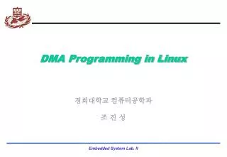
DMA Programming in Linux
DMA Programming in Linux. 경희대학교 컴퓨터공학과 조 진 성. 주요 내용. 주요내용 DMA 기본 소개 PXA255 에서의 DMA 제어기 DMA 프로그래밍 예제 PXA255 DMA 관련 레지스터. Direct memory access. Buffering Temporarily storing data in memory before processing Data accumulated in peripherals commonly buffered

DMA Programming in Linux
E N D
Presentation Transcript
DMA Programming in Linux 경희대학교 컴퓨터공학과 조 진 성
주요 내용 • 주요내용 • DMA 기본 소개 • PXA255에서의 DMA 제어기 • DMA 프로그래밍 예제 • PXA255 DMA관련 레지스터
Direct memory access • Buffering • Temporarily storing data in memory before processing • Data accumulated in peripherals commonly buffered • Microprocessor could handle this with ISR • Storing and restoring microprocessor state inefficient • Regular program must wait • DMA controller more efficient • Separate single-purpose processor • Microprocessor relinquishes control of system bus to DMA controller • Microprocessor can meanwhile execute its regular program • No inefficient storing and restoring state due to ISR call • Regular program need not wait unless it requires the system bus • Harvard archictecture – processor can fetch and execute instructions as long as they don’t access data memory – if they do, processor stalls
1(a): μP is executing its main program. 1(b): P1 receives input data in a register with address 0x8000. Time 2: P1 asserts Int to request servicing by the microprocessor. 3: After completing instruction at 100, μP sees Int asserted, saves the PC’s value of 100, and asserts Inta. 4: P1 detects Inta and puts interrupt address vector 16 on the data bus. 5(a): μP jumps to the address on the bus (16). The ISR there reads data from 0x8000 and then writes it to 0x0001, which is in memory. 5(b): After being read, P1 deasserts Int. 6: The ISR returns, thus restoring PC to 100+1=101, where μP resumes executing. Peripheral to memory transfer (DMA없이vectored interrupt 사용)
μP 1(a): P is executing its main program 1(b): P1 receives input data in a register with address 0x8000. Data memory Program memory 0x0000 0x0001 ISR 16: MOV R0, 0x8000 17: # modifies R0 System bus 18: MOV 0x0001, R0 19: RETI # ISR return ... Inta Main program P1 ... Int 16 100: instruction PC 101: instruction 0x8000 Peripheral to memory transfer (DMA없이vectored interrupt 사용)
μP 3: After completing instruction at 100, P sees Int asserted, saves the PC’s value of 100, and asserts Inta. Data memory Program memory 0x0000 0x0001 ISR 16: MOV R0, 0x8000 17: # modifies R0 System bus 18: MOV 0x0001, R0 19: RETI # ISR return ... 1 Inta Inta Main program P1 ... Int 16 100: instruction PC 101: instruction 0x8000 100 100 Peripheral to memory transfer (DMA없이vectored interrupt 사용)
μP 4: P1 detects Inta and puts interrupt address vector 16 on the data bus. Data memory Program memory 0x0000 0x0001 ISR 16: MOV R0, 0x8000 17: # modifies R0 System bus System bus 18: MOV 0x0001, R0 16 19: RETI # ISR return ... Inta Main program P1 ... Int 16 16 100: instruction PC 101: instruction 0x8000 100 Peripheral to memory transfer (DMA없이vectored interrupt 사용)
μP 5(a): P jumps to the address on the bus (16). The ISR there reads data from 0x8000 and then writes it to 0x0001, which is in memory. 5(b): After being read, P1 de-asserts Int. Data memory Data memory Program memory 0x0000 0x0001 0x0001 ISR ISR ISR 16: MOV R0, 0x8000 16: 16: MOV R0, 0x8000 MOV R0, 0x8000 17: # modifies R0 17: 17: # modifies R0 # modifies R0 System bus System bus 18: MOV 0x8001, R0 18: 18: MOV 0x0001, R0 MOV 0x8001, R0 19: RETI # ISR return RETI # ISR return RETI # ISR return ... 19: 19: ... ... Inta Main program P1 P1 ... Main program Main program Int ... ... 16 100: instruction PC 100: 100: instruction instruction 101: instruction 0x8000 0x8000 101: 101: instruction instruction 100 Int 0 Peripheral to memory transfer (DMA없이vectored interrupt 사용)
μP 6: The ISR returns, thus restoring PC to 100+1=101, where P resumes executing. Data memory Program memory 0x0000 0x0001 ISR 16: MOV R0, 0x8000 17: # modifies R0 System bus 18: MOV 0x8001, R0 19: RETI # ISR return ... Inta Main program P1 ... ISR Int 16 100: instruction 16: MOV R0, 0x8000 PC 101: instruction 0x8000 17: # modifies R0 +1 18: MOV 0x0001, R0 100 100 19: RETI # ISR return ... Main program ... 100: instruction 101: instruction Peripheral to memory transfer (DMA없이vectored interrupt 사용)
1(a): μP is executing its main program. It has already configured the DMA ctrl registers. 1(b): P1 receives input data in a register with address 0x8000. Time 3: DMA ctrl asserts Dreq to request control of system bus. 4: After executing instruction 100, μP sees Dreqasserted, releases the system bus, asserts Dack, and resumes execution. μP stalls only if it needs the system bus to continue executing. 2: P1 asserts req to request servicing by DMA ctrl. 5: (a) DMA ctrl asserts ack (b) reads data from 0x8000 and (b) writes that data to 0x0001. 6:. DMA de-asserts Dreq and ack completing handshake with P1. 7(a): μP de-asserts Dack and resumes control of the bus. 7(b): P1 de-asserts req. DMA를 이용한 Peripheral to memory transfer(1)
1(a): P is executing its main program. It has already configured the DMA ctrl registers 1(b): P1 receives input data in a register with address 0x8000. μP Data memory Program memory 0x0000 0x0001 No ISR needed! System bus ... Dack DMA ctrl P1 Main program Dreq ... ack 0x0001 100: instruction PC req 0x8000 0x8000 101: instruction 100 DMA를 이용한 Peripheral to memory transfer(2)
2: P1 asserts req to request servicing by DMA ctrl. 3: DMA ctrl asserts Dreq to request control of system bus μP Data memory Program memory 0x0000 0x0001 No ISR needed! System bus ... Dack DMA ctrl DMA ctrl P1 P1 P1 Main program Dreq ... ack 0x0001 100: instruction PC req 0x8000 0x8000 101: instruction 100 Dreq req 1 1 DMA를 이용한 Peripheral to memory transfer(3)
4: After executing instruction 100, P sees Dreq asserted, releases the system bus, asserts Dack, and resumes execution, P stalls only if it needs the system bus to continue executing. μP Data memory Program memory 0x0000 0x0001 No ISR needed! System bus 1 ... Dack Dack DMA ctrl P1 Main program Dreq ... ack 0x0001 100: instruction PC req 0x8000 0x8000 101: instruction 100 DMA를 이용한 Peripheral to memory transfer(4)
5: DMA ctrl (a) asserts ack, (b) reads data from 0x8000, and (c) writes that data to 0x0001. (Meanwhile, processor still executing if not stalled!) μP Data memory Program memory 0x0000 0x0001 No ISR needed! System bus ... Data memory Dack DMA ctrl P1 0x0000 0x0001 Main program Dreq ... ack 0x0001 100: instruction PC req 0x8000 0x8000 System bus 101: instruction 100 DMA ctrl P1 ack 0x0001 1 req 0x8000 ack 0x8000 DMA를 이용한 Peripheral to memory transfer(5)
6: DMA de-asserts Dreq and ack completing the handshake with P1. μP Data memory Program memory 0x0000 0x0001 No ISR needed! System bus ... Dack DMA ctrl P1 Main program Dreq ... ack 0x0001 100: instruction PC req 0x8000 0x8000 101: instruction 100 0 ack Dreq 0 DMA를 이용한 Peripheral to memory transfer(6)
Micro-processor System bus 7 Inta 5 Priority arbiter Peripheral1 Peripheral2 Int 3 2 2 Ireq1 Iack1 6 Ireq2 Iack2 Arbitration: Priority arbiter • Consider the situation where multiple peripherals request service from single resource (e.g., microprocessor, DMA controller) simultaneously - which gets serviced first? • Priority arbiter • Single-purpose processor • Peripherals make requests to arbiter, arbiter makes requests to resource • Arbiter connected to system bus for configuration only
Micro-processor System bus 7 Inta 5 Priority arbiter Peripheral1 Peripheral2 Int 3 2 2 Ireq1 Iack1 6 Ireq2 Iack2 Arbitration using a priority arbiter 1. Microprocessor is executing its program. 2. Peripheral1 needs servicing so asserts Ireq1. Peripheral2 also needs servicing so asserts Ireq2. 3. Priority arbiter sees at least one Ireq input asserted, so asserts Int. 4. Microprocessor stops executing its program and stores its state. 5. Microprocessor asserts Inta. 6. Priority arbiter asserts Iack1 to acknowledge Peripheral1. 7. Peripheral1 puts its interrupt address vector on the system bus 8. Microprocessor jumps to the address of ISR read from data bus, ISR executes and returns (and completes handshake with arbiter). 9. Microprocessor resumes executing its program.
Arbitration: Priority arbiter • Types of priority • Fixed priority • each peripheral has unique rank • highest rank chosen first with simultaneous requests • preferred when clear difference in rank between peripherals • Rotating priority (round-robin) • priority changed based on history of servicing • better distribution of servicing especially among peripherals with similar priority demands
P System bus Peripheral1 Peripheral2 Inta Ack_in Ack_out Ack_in Ack_out Int 0 Req_out Req_in Req_out Req_in Daisy-chain aware peripherals Arbitration: Daisy-chain arbitration • Arbitration done by peripherals • Built into peripheral or external logic added • req input and ack output added to each peripheral • Peripherals connected to each other in daisy-chain manner • One peripheral connected to resource, all others connected “upstream” • Peripheral’s req flows “downstream” to resource, resource’s ack flows “upstream” to requesting peripheral • Closest peripheral has highest priority
Micro-processor P System bus System bus Inta Peripheral1 Peripheral2 Priority arbiter Peripheral1 Peripheral2 Inta Int Ack_in Ack_out Ack_in Ack_out Int 0 Req_out Req_in Req_out Req_in Ireq1 Iack1 Ireq2 Daisy-chain aware peripherals Iack2 Arbitration: Daisy-chain arbitration • Pros/cons • Easy to add/remove peripheral - no system redesign needed • Does not support rotating priority • One broken peripheral can cause loss of access to other peripherals
DMA Controller(DMAC) - PXA255 • DMAC는 내부 및 외부 주변장치에 의해 발생된 요청에 대한 응답으로 메인 메모리로 혹은 메인 메모리로부터 데이터를 전달 • DMAC는 16개의 DMA channels 지원 • DMAC는 flow-through transfers만을 지원 • Flow-through data는 데이터가 목적지에 저장되기 전에 DMAC를 통해 전달됨 • DMAC는 flow-through transfers를 이용해서 memory-to-memory moves를 수행할 수 있음 • DMAC Channels • 각 채널은 4개의 32-bit registers에 의해 제어 • 각 채널은 내부/외부 장치중의 하나를 서비스하도록 구성 • Each channel is serviced in increments of the peripheral device’s burst size • Each channel is delivered in the granularity appropriate to that device’s port width.
DMA Channel • The burst size and port width for each device is programmed in the channel registers and is based on the device’s FIFO depth and bandwidth needs. • When multiple channels are actively executing, the DMAC services each channel is serviced with a burst of data. After the data burst is sent, the DMAC may perform a context switch to another active channel. The DMAC performs context switches based on a channel’s activity, whether its target device is currently requesting service, and where that channel lies in the priority scheme. • Channel information must be maintained on a per-channel basis and is contained in the DMAC registers see in Table 5-13, “DMA Controller Registers” on page 5-28. • The DMAC supports two methods of loading the DMAC register, No-Descriptor and Descriptor Fetch Modes. • Software must ensure cache coherency when it configures the DMA channels.
Memory Controller System Bus(internal) DMA Controller Control Register 16 DMA Channels Channel 15 DSCR 0 Channel 0 DREQ[1:0] (external) DDADR 0 DSADR 0 DMA_IRQ (internal) DRCMR 0 DTADR 0 DCMD 0 DINT PREQ[37:0] (internal) Peripheral Bus(internal) DMAC Block Diagram
DMA Signal Descriptions • The DREQ[1:0], PREQ[37:0] and DMA_IRQ signals are controlled by the DMAC • The DREQ[1:0] signal must remain asserted for four MEMCLKs to allow the DMA to recognize the 0 to 1 transition. • When the DREQ[1:0] signals are deasserted, they must remain deasserted for at least four MEMCLKs. • The DMAC registers the transition from 0 to 1 to identify a new request. • The external companion chip must not assert another DREQ until the previous DMA data transfer starts
DMA Signal Descriptions • The DREQ[1:0], PREQ[37:0] and DMA_IRQ signals are controlled by the DMAC
DMA_IRQ Signal • The application processor has 16 IRQ signals, one for each DMA channel. • Each DMA IRQ can be read in the DINT register. • The user can mask some bits that cause interrupts on a channel, such as ENDIRQEN, STARTIRQEN, and STOPIRQEN. • When DMA interrupt occurs, it is visible in Pending Interrupt Register Bit . • When a pending interrupt becomes active, it is sent to the CPU if its corresponding ICMR mask Bit.
DMA Channel Priority Scheme • The DMA channel priority scheme allows peripherals that require high bandwidth to be serviced more often than those requiring less bandwidth. • The DMA channels are internally divided into four sets. • Each set contains four channels. • The channels get a round-robin priority in each set. • Set zero has the highest priority. • Set 1 has higher priority than sets two and three. • Sets two and three are low priority sets. • High bandwidth peripherals must be programmed in set zero. • Memory-to-memory moves and low bandwidth peripherals must be programmed in set two or three. • When all channels are running concurrently, set zero is serviced four times out of any eight consecutive channel servicing instances. Set one is serviced twice and sets two and three are each serviced once.
DMA Channel Priority Scheme(2) • If all channels request data transfers, the Sets are prioritized in following order: • Set zero -> Set one -> Set zero -> Set two -> Set zero -> Set one -> Set zero -> Set three
DMA Descriptors • DMAC 동작모드 • Descriptor Fetch Mode와 No-Descriptor Fetch Mode • 모드는 DCSRx[NODESCFETCH] bit에 의해 결정 • 모드는 각 채널에 대해 독립적으로 동시에 사용 가능 • 각 채널은 동작모드를 바꿀 때는 일단 정지해야만 함
No-Descriptor Fetch Mode • DDADRx is reserved. • Software must not write to the DDADRx and must load the DSADRx, DTADRx, and DCMDx registers. • When the Run bit is set, the DMAC immediately begins to transfer data • The channel stops when it finishes the transfer.
No-Descriptor Fetch Mode 1. The channel is in an uninitialized state after reset. 2. The DCSR[RUN] bit is set to a 0 and the DCSR[NODESCFETCH] bit is set to a 1. 3. The software writes a source address to the DSADR register, a target address to the DTADR register, and a command to the DCMD register. The DDADR register is reserved in this No-Descriptor Fetch Mode and must not be written. 4. The software writes a 1 to the DCSR[RUN] bit and the No-Descriptor fetches are performed. 5. The channel waits for the request or starts the data transfer, as determined by the DCMD[FLOW] source and target bits. 6. The channel transmits a number of bytes equal to the smaller of DCMD[SIZE] and DCMD[LENGTH]. 7. The channel waits for the next request or continues with the data transfer until the DCMD[LENGTH] reaches zero. 8. The DDADR[STOP] is set to a 1 and the channel stops.
Descriptor Fetch Mode • DMAC registers are loaded from DMA descriptors in main memory. • Multiple DMA descriptors can be chained together in a list. • The descriptor’s protocol design allows descriptors to be added efficiently to the descriptor list of a running DMA stream.
Descriptor Fetch Mode 1. The channel is in an uninitialized state after reset. 2. The software writes a descriptor address (aligned to a 16-byte boundary) to the DDADR register. 3. The software writes a 1 to the DCSR[RUN] bit. 4. The DMAC fetches the four-word descriptor from the memory indicated by DDADR. 5. The four-word DMA descriptor, aligned on a 16-byte boundary in main memory, loads the following registers: a. Word [0] -> DDADRx register and a single flag bit. Points to the next four-word descriptor. b. Word [1] -> DSADRx register for the current transfer. c. Word [2] -> DTADRx register for the current transfer. d. Word [3] -> DCMDx register for the current transfer.
Descriptor Fetch Mode 6. The channel waits for the request or starts the data transfer, as determined by the DCMD[FLOW] source and target bits. 7. The channel transmits a number of bytes equal to the smaller of DCMD[SIZE] and DCMD[LENGTH]. 8. The channel waits for the next request or continues with the data transfer until the DCMD[LENGTH] reaches zero. 9. The channel stops or continues with a new descriptor fetch from the memory, as determined by the DDADR[STOP] bit. • Software must set the DCSR[RUN] bit to 1 after it loads the DDADR. The channel descriptor fetch does not take place unless the DDADR register is loaded and the DCSR[RUN] bit is set to a 1. The DMAC priority scheme does not affect DMA descriptor fetches. The next descriptor is fetched immediately after the previous descriptor is serviced
Byte Transfer Order • The DCMD[ENDIAN] bit indicates the byte ordering in a word when data is read from or written to memory. • The DCMD[ENDIAN] bit must be set to 0, which is little endian transfers. • If data is being transferred from an internal device to memory, DCMD[ENDIAN] is set to a 0, and DCMD[SIZE] is set to a 1, the memory receives the data in the following order: • 1. Byte[0] • 2. Byte[1] • 3. Byte[2] • 4. Byte[3]
Servicing Internal Peripherals • The DMAC provides the DMA Request to Channel Map Registers (DRCMRx) that contain four bits used to assign a channel number for each possible DMA request. An internal peripheral can be mapped to any of the 16 available channels.
Using Flow-Through DMA Read Cycles to Service Internal Peripherals • A flow-through DMA read for an internal peripheral begins when the internal peripheral sends a request, via the PREQ bus, to a DMAC channel that is running and configured for a flow-through read. The number of bytes to be transferred is specified with DCMDx[SIZE]. When the request is the highest priority request, the following process begins: 1. The DMAC sends the memory controller a request to read the number of bytes addressed by DSADRx[31:0] into a 32-byte staging buffer in the DMAC. 2. The DMAC transfers the data to the I/O device addressed in DTADRx[31:0]. DCMD[WIDTH] specifies the width of the internal peripheral to which the data is transferred. 3. At the end of the transfer, DSADRx is increased by the smaller value of DCMDx[LENGTH] and DCMD[SIZE]. DCMDx[LENGTH] is decreased by the same value.
Using Flow-Through DMA Read Cycles to Service Internal Peripherals • For a flow-through DMA read to an internal peripheral, use the following settings for the DMAC register bits: • DSADR[SRCADDR] = external memory address • DTADR[TRGADDR] = internal peripheral’s address • DCMD[INCSRCADDR] = 1 • DCMD[FLOWSRC] = 0 • DCMD[FLOWTRG] = 1
Using Flow-Through DMA Write Cycles to Service Internal Peripherals • A flow-through DMA write for an internal peripheral begins when the internal peripheral sends a request, via the PREQ bus, to a DMAC channel that is running and configured for a flow-through write. The number of bytes to be transferred are specified with DCMDx[SIZE]. When the request is the highest priority request, the following process begins: 1. The DMAC transfers the required number of bytes from the I/O device addressed by DSADRx[31:0] to the DMAC write buffer. 2. The DMAC transfers the data to the memory controller via the internal bus. DCMD[WIDTH] specifies the width of the internal peripheral to which the transfer is being made. 3. At the end of the transfer, DTADRx is increased by the smaller value of DCMDx[LENGTH] and DCMD[SIZE]. DCMDx[LENGTH] is decreased by the same number.
Using Flow-Through DMA Write Cycles to Service Internal Peripherals • For a flow-through DMA write to an internal peripheral, use the following settings for the DMAC register bits: • DSADR[SRCADDR] = internal peripheral address • DTADR[TRGADDR] = external memory address • DCMD[INCTRGADDR] = 1 • DCMD[FLOWSRC] = 1 • DCMD[FLOWTRG] = 0
Using Flow-Through DMA Write Cycles to Service Internal Peripherals • A flow-through DMA read for an external peripheral begins when the external peripheral sends a request, via the DREQ[1:0] bus, to a DMAC channel that is running and configured for a flow-through read. DCMDx[SIZE] specifies the number of bytes to be transferred. When the request is the highest priority request, the follow process begins. 1. The DMAC sends a request to the memory controller to read the number of bytes addressed by DSADRx[31:0] into a 32-byte staging buffer in the DMAC. 2. The DMAC transfers the data in the buffer to the external device addressed in DTADRx[31:0]. 3. At the end of the transfer, DSADRx is increased by the smaller value of DCMDx[LENGTH] and DCMD[SIZE]. DCMDx[LENGTH] is decreased by the same value. • Note: The process shown for a flow-through DMA read to an external peripheral indicates that the external address increases. Some external peripherals, such as FIFOs, do not require an increment in the external address.
Using Flow-Through DMA Read Cycles to Service External Peripherals • For a flow-through DMA read to an external peripheral, use the following settings for the DMAC register bits: • DSADR[SRCADDR] = external memory address • DTADR[TRGADDR] = companion chip’s address • DCMD[INCSRCADDR] = 1 • DCMD[INCTRGADDR] = 0 • DCMD[FLOWSRC] = 0 • DCMD[FLOWTRG] = 1
Using Flow-Through DMA Write Cycles to Service External Peripherals • A flow-through DMA write to an external peripheral begins when the external peripheral sends a request, via the DREQ bus, to a DMAC channel that is running and configured for a flow-through write. DCMDx[SIZE] specifies the number of bytes to be transferred. When the request is the highest priority request, the following process begins: 1. The DMAC transfers the required number of bytes from the I/O device addressed by DSADRx[31:0] to the DMAC write buffer. 2. The DMAC transfers the data to the memory controller via the internal bus. 3. At the end of the transfer, DTADRx is increased by the smaller value of DCMDx[LENGTH] and DCMD[SIZE]. DCMDx[LENGTH] is decreased by the same number. • Note:The process shown for a flow-through DMA write to an external peripheral indicates that the external address increases. Some external peripherals, such as FIFOs, do not require an increment in the external address.
Using Flow-Through DMA Write Cycles to Service External Peripherals • For a flow-through DMA write to an external peripheral, use the following settings for the DMAC register bits: • DSADR[SRCADDR] = companion chip address • DTADR[TRGADDR] = external memory address. • DCMD[INCSRCADDR] = 0 • DCMD[INCTRGADDR] = 1 • DCMD[FLOWSRC] = 1 • DCMD[FLOWTRG] = 0
Memory-to-Memory Moves • Memory-to-memory moves do not involve the DREQ and PREQ request signals. • The processor writes to the DCSR[RUN] bit and a channel is configured for a memory-to-memory move. • The DCMDx[FLOWSRC] and the DCMD[FLOWTRG] bits must be set to 0. • If DCMD[IRQEN] is set to a 1, a DMA interrupt is requested at the end of the last cycle associated with the byte that caused DCMDx[LENGTH] to decrease from 1 to 0.
Memory-to-Memory Moves • A flow-through DMA memory-to-memory read or write goes through the following steps: 1. The processor writes to the DCSR[RUN] register bit and starts the memory-to-memory moves. 2. If the application processor is in the Descriptor Fetch Mode, the channel configured for the move fetches the four-word descriptor. The channel transfers data without waiting for PREQ or DREQ to be asserted. The smaller value of DCMDx[SIZE] or DCMDx[LENGTH] specifies the number of bytes to be transferred. 3. The DMAC sends a request to the memory controller to read the number of bytes addressed by DSADRx[31:0] into a 32-byte staging buffer in the DMAC. 4. The DMAC generates a write cycle to the location addressed in DTADRx[31:0]. 5. At the end of the transfer, DSADRx and DTADRx are increased by the smaller value of DCMD[SIZE] and DCMDx[LENGTH]. If DCMD[SIZE] is smaller than DCMDx[LENGTH], DCMDx[LENGTH] is decreased by DCMD[SIZE]. If DCMD[SIZE] is equal to or larger than DCMDx[LENGTH], DCMDx[LENGTH] is zero.
Memory-to-Memory Moves • For a memory-to-memory read or write, use the following settings for the DMAC registers: • DSADR[SRCADDR] = external memory address • DTADR[TRGADDR] = external memory address • DCMD[INCSRCADDR] = 1 • DCMD[INCTRGADDR] = 1 • DCMD[FLOWSRC] = 0 • DCMD[FLOWTRG] = 0 • DCSR[RUN] =1
Using Flow-Through DMA Write Cycles to Service External Peripherals • For a flow-through DMA write to an external peripheral, use the following settings for the DMAC register bits: • DSADR[SRCADDR] = companion chip address • DTADR[TRGADDR] = external memory address. • DCMD[INCSRCADDR] = 0 • DCMD[INCTRGADDR] = 1 • DCMD[FLOWSRC] = 1 • DCMD[FLOWTRG] = 0
DMA 예제 프로그램 • 기본적인 DMA 동작을 이해하기 위한 프로그램 작성 • Memory-to-Memory Data transfer를 위한 sample code 작성