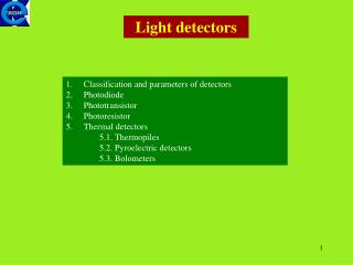
Detectors for Light Sources
Detectors for Light Sources. Contribution to the eXtreme Data Workshop of Nicola Tartoni Diamond Light Source. Outline. Anatomy of detectors Computing inside detectors Escalation of data volume A view of the future: feedback. Detector. Radiation field. Digital data. Source.

Detectors for Light Sources
E N D
Presentation Transcript
Detectors for Light Sources Contribution to the eXtreme Data Workshop of Nicola Tartoni Diamond Light Source
Outline • Anatomy of detectors • Computing inside detectors • Escalation of data volume • A view of the future: feedback
Detector Radiation field Digital data Source Data storage
Detector Digital Data Processing Photon converter/ /Sensor Signal conditioning Digital conversion
Photon converter/sensor converts X-ray energy to electric charge. X-ray energy can be converted directly to electric charge (e.g. semiconductor detectors) or indirectly (e.g. phosphors + light sensors). • Signal conditioning electronics converts the electric charge generated by the sensor to a voltage signal. It improves the signal to noise ratio. • Digital conversion converts the voltage signal to digital. Can be analogue to digital converter, discriminators coupled to counters, a combination of various systems.
Digital Data Processing • Digital filtersimprovement of S/N in spectroscopy detectors • Data correction dead time correction, flat field correction • Data formatting hystogramming,, image frame • Data compression • Information extraction autocorrelation function, peak fitting to deconvolute overlapping peaks
Output of signal conditioning electronics Output of digital data processing
Output of preamps continuously sampled • ADC XpressII: 80 Mhz sampling rate, 14 bits resolution. • Trigger event • Adaptive filter • Correction of the slope • Correction of artefacts such as reset cross talk • Reset inhibit signal for each channel
Ge monolithic multielement (8x8) detector head Digital conversion and pulse processing Matrix of resolution during a qualification test
X-ray Fluorescence detectors • X-ray Fluorescence detectors could have hundreds of channels not far in the future. • A typical X-ray Fluorescence map (e.g. elemental analysis) contains over 10,000 MCA spectra. • The MAIA detector (Brookhaven development) has implemented on the fly data processing as well as piping data to analysis packages for near real time data analysis. • “The ability to rapidly stream the data to an external processing system, to store the data in efficient file formats and incorporation of some degree of automation is highly desirable” • (Fred Mosselmans I18 PBS)
Mosaic of 9 CCD sensors • Pixel size: 51 um x 51 um • No. of Pixels: 6144 x 6144 • ADC depth: 16 bits • Read-out time: 1.1 s • Image size: 72 MB • Binned image size: ~20 MB • Data set per sample: ~ 300-400 images • “Volume” of a data set: ~ 6-8 GB
Hybrid detector, 60 monolithic silicon sensors, • Pixel size: 172 um • No. of Pixels: 2463 x 2527 • Counter depth: 20 bits • Frame rate:12 fps • Image size (Tif 32 bits): ~23 MB • Compressed image: ~ 6 MB • Data set: ~ 1800 images • “Volume” of a data set:11 GB • P6M recently upgraded to 25 fps • Future development P6M to 100 fps Single module 8x2 chips 172 µm x 172 µm pixels P6M 5x12 modules ~ 43x45 cm2
Detector for long-wavelength macromolecular crystallography beamline I23. • In-vacuum detector (10-7 mbar) • 120 P100k modules in semi-cylindrical geometry • 24 banks, 5 modules wide • Delivery spring 2013. Pilatus 12M • Assumption 2 x 180 deg in different orientations, 0.1 deg oscillation 3600 images • Image size: 12.0 MB • Estimated data set size: 12.0 MB x 3600 ~ 43.2 GB • 48 samples in 24 hours • Over 2 TB per day
EXCALIBUREnhanced X-ray CAmera for Live Imaging and BURst mode operation DLS/STFC Developmentproject 10 cm
EXCALIBUR 3 modules 3M pixels (11 x 10 cm) 8x2 MPX3/module 1 FPGA card / row of 8 MPX3s Front-End Module (FEM) FPGA card • Readout backend: 6 Linux nodes • Buffering, local storage & processing of image data • Interface to EPICS for DAQ & control
Connect a brain to your eye Feedback Observation Action command Understanding • An “intelligent” board can open up a completely new realm for detectors: • THE DETECTOR WILL DRIVE THE EXPERIMENT! • Real time calculation (e.g. autocorrelation function) • Pattern recognition • Variable integration time as a function of photon flux • Feedback to the diffractometer, sample environment, other instruments
Detectors in 20 years will no longer look the same because of the computing power that will be embedded. • Detector and beam line scientists and users look forward to future developments in computing.