Internet Protocol (IP) Fundamentals for Network Design
1.36k likes | 1.4k Vues
Explore the basics of networking, IP addressing, routing, and internetwork design. Learn about Ethernet, TCP/IP, subnetting, and more in this concise guide to network fundamentals.

Internet Protocol (IP) Fundamentals for Network Design
E N D
Presentation Transcript
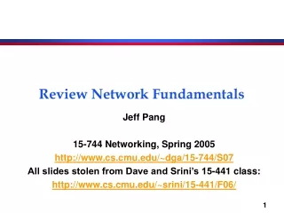
Review Network Fundamentals Jeff Pang 15-744 Networking, Spring 2005 http://www.cs.cmu.edu/~dga/15-744/S07 All slides stolen from Dave and Srini’s 15-441 class: http://www.cs.cmu.edu/~srini/15-441/F06/
email WWW phone... SMTP HTTP RTP... TCP UDP… IP ethernet PPP… CSMA async sonet... copper fiber radio... Host Host Wireless Host Host Host Ethernet Framerelay Ethernet Host Host Host IP/SONET ATM Host 802.X Ethernet Host Host Host Host Host Host All You Need to Know in 1 Slide Ethernet, CSMA/CD Bridges, Switches, Spanning Tree Bandwidth x Delay TCP Performance IP Blocks, CIDR, Subnets Longest Prefix Match, Fragmentation, MTU RIP, OSFP Distance Vector Link-State Modulation Coding FDMA, TDMA Tier 3 Tier 2 BGP Tier 2 The Internet Tier 1 Tier 1 Tier 2
A More Conventional Overview • IP Addressing • IP Forwarding • IP Packet Format • IP Routing • Performance Calculations • Link Layer Stuff • Physical Layer Stuff
What is an Internetwork? • Multiple incompatible LANs can be physically connected by specialized computers called routers • The connected networks are called an internetwork • The “Internet” is one (very big & successful) example of an internetwork ... ... host host host host host host LAN 1 LAN 2 router router router WAN WAN LAN 1 and LAN 2 might be completely different, totally incompatible LANs (e.g., Ethernet and ATM)
Logical Structure of Internet host • Ad hoc interconnection of networks • No particular topology • Vastly different router & link capacities • Send packets from source to destination by hopping through networks • Router connect one network to another • Different paths to destination may exist router router router host router router router
email WWW phone... SMTP HTTP RTP... TCP UDP… IP ethernet PPP… CSMA async sonet... copper fiber radio... Internet Protocol (IP) • Hour Glass Model • Create abstraction layer that hides underlying technology from network application software • Make as minimal as possible • Allows range of current & future technologies • Can support many different types of applications Network applications Network technology
Problem 3: Internetwork Design ... ... host host host host host host • How do I designate a distant host? • Addressing / naming • How do I send information to a distant host? • What gets sent? • What route should it take? • Must support: • Heterogeneity LAN technologies • Scalability ensure ability to grow to worldwide scale LAN 1 LAN 2 router router router WAN WAN
Getting to a Destination • How do you get driving directions? • Intersectionsrouters • Roadslinks/networks • Roads change slowly
Addressing in IP • IP addresses are names of interfaces • E.g., 128.2.1.1 • Domain Name System (DNS) names are names of hosts • E.g., www.cmu.edu • DNS binds host names to interfaces • Routing binds interface names to paths
Router Table Size • One entry for every host on the Internet • 440M (7/06) entries,doubling every 2.5 years • One entry for every LAN • Every host on LAN shares prefix • Still too many and growing quickly • One entry for every organization • Every host in organization shares prefix • Requires careful address allocation
IP Addresses • Fixed length: 32 bits • Initial classful structure (1981) (not relevant now!!!) • Total IP address size: 4 billion • Class A: 128 networks, 16M hosts • Class B: 16K networks, 64K hosts • Class C: 2M networks, 256 hosts High Order Bits 0 10 110 Format 7 bits of net, 24 bits of host 14 bits of net, 16 bits of host 21 bits of net, 8 bits of host Class A B C
IP Address Classes(Some are Obsolete) Network ID Host ID 8 16 24 32 Class A Network ID 0 Host ID Class B 10 Class C 110 Class D Multicast Addresses 1110 Class E 1111 Reserved for experiments
Original IP Route Lookup • Address would specify prefix for forwarding table • Simple lookup • www.cmu.edu address 128.2.11.43 • Class B address – class + network is 128.2 • Lookup 128.2 in forwarding table • Prefix – part of address that really matters for routing • Forwarding table contains • List of class+network entries • A few fixed prefix lengths (8/16/24) • Large tables • 2 Million class C networks
Subnet AddressingRFC917 (1984) • Class A & B networks too big • Very few LANs have close to 64K hosts • For electrical/LAN limitations, performance or administrative reasons • Need simple way to get multiple “networks” • Use bridging, multiple IP networks or split up single network address ranges (subnet) • CMU case study in RFC • Chose not to adopt – concern that it would not be widely supported
Subnetting • Add another layer to hierarchy • Variable length subnet masks • Could subnet a class B into several chunks Network Host Network Subnet Host SubnetMask 0 0 0 0 0 0 0 0 1 1 1 1 1 1 1 1 1 1 1 1 1 1 1 1 1 1 1 1 1 1 1 1
Forwarding Example • Assume a packet arrives with address 150.100.12.176 • Step 1: AND address with class + subnet mask 150.100.12.154 150.100.12.176 H1 H2 150.100.12.128 150.100.12.129 150.100.12.24 150.100.12.55 150.100.0.1 R1 H3 H4 To Internet 150.100.12.4 150.100.12.0
IP Address Problem (1991) • Address space depletion • In danger of running out of classes A and B • Why? • Class C too small for most domains • Very few class A – very careful about giving them out • Class B – greatest problem • Class B sparsely populated • But people refuse to give it back • Large forwarding tables • 2 Million possible class C groups
IP Address Utilization (‘97) http://www.caida.org/outreach/resources/learn/ipv4space/
Important Concepts • Hierarchical addressing critical for scalable system • Don’t require everyone to know everyone else • Reduces number of updates when something changes
Classless Inter-Domain Routing(CIDR) – RFC1338 • Allows arbitrary split between network & host part of address • Do not use classes to determine network ID • Use common part of address as network number • E.g., addresses 192.4.16 - 192.4.31 have the first 20 bits in common. Thus, we use these 20 bits as the network number 192.4.16/20 • Enables more efficient usage of address space (and router tables) How? • Use single entry for range in forwarding tables • Combined forwarding entries when possible
IP Addresses: How to Get One? • How does an ISP get block of addresses? • From Regional Internet Registries (RIRs) • ARIN (North America, Southern Africa), APNIC (Asia-Pacific), RIPE (Europe, Northern Africa), LACNIC (South America) • How about a single host? • Hard-coded by system admin in a file • DHCP:Dynamic Host Configuration Protocol: dynamically get address: “plug-and-play” • Host broadcasts “DHCP discover” msg • DHCP server responds with “DHCP offer” msg • Host requests IP address: “DHCP request” msg • DHCP server sends address: “DHCP ack” msg
Host Routing Table Example Destination Gateway Genmask Iface 128.2.209.100 0.0.0.0 255.255.255.255 eth0 128.2.0.0 0.0.0.0 255.255.0.0 eth0 127.0.0.0 0.0.0.0 255.0.0.0 lo 0.0.0.0 128.2.254.36 0.0.0.0 eth0 • From “netstat –rn” • Host 128.2.209.100 when plugged into CS ethernet • Dest 128.2.209.100 routing to same machine • Dest 128.2.0.0 other hosts on same ethernet • Dest 127.0.0.0 special loopback address • Dest 0.0.0.0 default route to rest of Internet • Main CS router: gigrouter.net.cs.cmu.edu (128.2.254.36)
Routing to the Network • Packet to 10.1.1.3 arrives • Path is R2 – R1 – H1 – H2 10.1.1.2 10.1.1.4 10.1.1.3 H1 H2 10.1.1/24 10.1.0.2 10.1.0.1 10.1.1.1 10.1.2.2 R1 H3 10.1.0/24 10.1.2/23 10.1/16 10.1.8/24 R2 Provider 10.1.8.1 10.1.2.1 10.1.16.1 H4 10.1.8.4
Routing Within the Subnet • Packet to 10.1.1.3 • Matches 10.1.0.0/23 10.1.1.2 10.1.1.4 10.1.1.3 H1 H2 10.1.1/24 Routing table at R2 10.1.0.2 10.1.0.1 10.1.1.1 10.1.2.2 R1 H3 Destination Next Hop Interface 10.1.0/24 127.0.0.1 127.0.0.1 lo0 10.1.2/23 Default or 0/0 provider 10.1.16.1 10.1/16 10.1.8/24 R2 10.1.8.0/24 10.1.8.1 10.1.8.1 10.1.8.1 10.1.2.1 10.1.16.1 10.1.2.0/23 10.1.2.1 10.1.2.1 H4 10.1.0.0/23 10.1.2.2 10.1.2.1 10.1.8.4
Routing Within the Subnet • Packet to 10.1.1.3 • Matches 10.1.1.1/31 • Longest prefix match 10.1.1.2 10.1.1.4 10.1.1.3 H1 H2 10.1.1/24 10.1.0.2 10.1.0.1 10.1.1.1 10.1.2.2 R1 H3 Routing table at R1 10.1.0/24 Destination Next Hop Interface 127.0.0.1 127.0.0.1 lo0 10.1.2/23 10.1/16 10.1.8/24 R2 Default or 0/0 10.1.2.1 10.1.2.2 10.1.0.0/24 10.1.0.1 10.1.0.1 10.1.8.1 10.1.2.1 10.1.16.1 H4 10.1.1.0/24 10.1.1.1 10.1.1.4 10.1.8.4 10.1.2.0/23 10.1.2.2 10.1.2.2 10.1.1.2/31 10.1.1.2 10.1.1.2
Routing Within the Subnet • Packet to 10.1.1.3 • Direct route • Longest prefix match 10.1.1.2 10.1.1.4 10.1.1.3 H1 H2 10.1.1/24 10.1.0.2 10.1.0.1 10.1.1.1 10.1.2.2 R1 H3 Routing table at H1 10.1.0/24 Destination Next Hop Interface 10.1.2/23 127.0.0.1 127.0.0.1 lo0 10.1/16 10.1.8/24 R2 Default or 0/0 10.1.1.1 10.1.1.2 10.1.8.1 10.1.2.1 10.1.16.1 10.1.1.0/24 10.1.1.2 10.1.1.1 H4 10.1.1.3/31 10.1.1.2 10.1.1.2 10.1.8.4
0 4 8 12 16 19 24 28 31 version HLen TOS Length Identifier Flag Offset TTL Protocol Checksum Source Address Destination Address Options (if any) Data IP Service Model • Low-level communication model provided by Internet • Datagram • Each packet self-contained • All information needed to get to destination • No advance setup or connection maintenance • Analogous to letter or telegram IPv4 Packet Format Header
Version: IP Version 4 for IPv4 HLen: Header Length 32-bit words (typically 5) TOS: Type of Service Priority information Length: Packet Length Bytes (including header) Header format can change with versions First byte identifies version Length field limits packets to 65,535 bytes In practice, break into much smaller packets for network performance considerations ver- sion HLen TOS Length Identifier Flags Offset TTL Protocol Checksum Source Address Destination Address 0 4 8 12 16 19 24 28 31 Options (if any) Data IPv4 Header Fields
ver- sion HLen TOS Length Identifier Flags Offset TTL Protocol Checksum Source Address Destination Address 0 4 8 12 16 19 24 28 31 Options (if any) Data IPv4 Header Fields • Identifier, flags, fragment offset used primarily for fragmentation • Time to live • Must be decremented at each router • Packets with TTL=0 are thrown away • Ensure packets exit the network • Protocol • Demultiplexing to higher layer protocols • TCP = 6, ICMP = 1, UDP = 17… • Header checksum • Ensures some degree of header integrity • Relatively weak – 16 bit • Options • E.g. Source routing, record route, etc. • Performance issues • Poorly supported
Source Address 32-bit IP address of sender Destination Address 32-bit IP address of destination Like the addresses on an envelope Globally unique identification of sender & receiver ver- sion HLen TOS Length Identifier Flags Offset TTL Protocol Checksum Source Address Destination Address 0 4 8 12 16 19 24 28 31 Options (if any) Data IPv4 Header Fields
IP Fragmentation MTU = 2000 host • Every network has own Maximum Transmission Unit (MTU) • Largest IP datagram it can carry within its own packet frame • E.g., Ethernet is 1500 bytes • Don’t know MTUs of all intermediate networks in advance • IP Solution • When hit network with small MTU, fragment packets router router MTU = 1500 host MTU = 4000
Reassembly • Where to do reassembly? • End nodes or at routers? • End nodes • Avoids unnecessary work where large packets are fragmented multiple times • If any fragment missing, delete entire packet • Dangerous to do at intermediate nodes • How much buffer space required at routers? • What if routes in network change? • Multiple paths through network • All fragments only required to go through destination
Fragmentation and Reassembly Concepts • Demonstrates many Internet concepts • Decentralized • Every network can choose MTU • Connectionless • Each (fragment of) packet contains full routing information • Fragments can proceed independently and along different routes • Best effort • Fail by dropping packet • Destination can give up on reassembly • No need to signal sender that failure occurred • Complex endpoints and simple routers • Reassembly at endpoints
Fragmentation is Harmful • Uses resources poorly • Forwarding costs per packet • Best if we can send large chunks of data • Worst case: packet just bigger than MTU • Poor end-to-end performance • Loss of a fragment • Path MTU discovery protocol determines minimum MTU along route • Uses ICMP error messages • Common theme in system design • Assure correctness by implementing complete protocol • Optimize common cases to avoid full complexity
Internet Control Message Protocol (ICMP) • Short messages used to send error & other control information • Examples • Ping request / response • Can use to check whether remote host reachable • Destination unreachable • Indicates how packet got & why couldn’t go further • Flow control • Slow down packet delivery rate • Redirect • Suggest alternate routing path for future messages • Router solicitation / advertisement • Helps newly connected host discover local router • Timeout • Packet exceeded maximum hop limit
IP MTU Discovery with ICMP MTU = 2000 host • Typically send series of packets from one host to another • Typically, all will follow same route • Routes remain stable for minutes at a time • Makes sense to determine path MTU before sending real packets • Operation • Send max-sized packet with “do not fragment” flag set • If encounters problem, ICMP message will be returned • “Destination unreachable: Fragmentation needed” • Usually indicates MTU encountered router router MTU = 1500 host MTU = 4000
Important Concepts • Base-level protocol (IP) provides minimal service level • Allows highly decentralized implementation • Each step involves determining next hop • Most of the work at the endpoints • ICMP provides low-level error reporting • IP forwarding global addressing, alternatives, lookup tables • IP addressing hierarchical, CIDR • IP service best effort, simplicity of routers • IP packets header fields, fragmentation, ICMP
Router IP Forwarding • The Story So Far… • IP addresses are structure to reflect Internet structure • IP packet headers carry these addresses • When Packet Arrives at Router • Examine header to determine intended destination • Look up in table to determine next hop in path • Send packet out appropriate port • This/next lecture • How to generate the forwarding table
Graph Model • Represent each router as node • Direct link between routers represented by edge • Symmetric links undirected graph • Edge “cost” c(x,y) denotes measure of difficulty of using link • delay, $ cost, or congestion level • Task • Determine least cost path from every node to every other node • Path cost d(x,y) = sum of link costs E C 3 1 F 1 2 6 1 D 3 A 4 B
Routes from Node A E C 3 1 • Properties • Some set of shortest paths forms tree • Shortest path spanning tree • Solution not unique • E.g., A-E-F-C-D also has cost 7 F 1 2 6 1 D 3 A 4 B
Ways to Compute Shortest Paths • Centralized • Collect graph structure in one place • Use standard graph algorithm • Disseminate routing tables • Link-state • Every node collects complete graph structure • Each computes shortest paths from it • Each generates own routing table • Distance-vector • No one has copy of graph • Nodes construct their own tables iteratively • Each sends information about its table to neighbors
Outline • Distance Vector • Link State • Routing Hierarchy • BGP
Distance-Vector Method E C 3 • Idea • At any time, have cost/next hop of best known path to destination • Use cost when no path known • Initially • Only have entries for directly connected nodes 1 F 1 2 6 1 D 3 A 4 B
Distance-Vector Update z d(z,y) • Update(x,y,z) d c(x,z) + d(z,y) # Cost of path from x to y with first hop z if d < d(x,y) # Found better path return d,z# Updated cost / next hop else return d(x,y), nexthop(x,y) # Existing cost / next hop c(x,z) y x d(x,y)
Algorithm • Bellman-Ford algorithm • Repeat For every node x For every neighbor z For every destination y d(x,y) Update(x,y,z) • Until converge
1 4 1 50 X Z Y Distance Vector: Link Cost Changes Link cost changes: • Node detects local link cost change • Updates distance table • If cost change in least cost path, notify neighbors algorithm terminates “good news travels fast”