
ABSTRACT
PENN UAV HARDWARE OVERVIEW. SYSTEM FLOWCHART. SOFTWARE FLOWCHART. ¼ Scale Piper J3 Cub UAVs. Visual Tracking of an Unmanned Aerial Vehicle (UAV) Using GPS. CloudCap Piccolo Onboard Avionics (10 Hz GPS, 100Hz IMU). SYSTEM SPECIFICATIONS.

ABSTRACT
E N D
Presentation Transcript
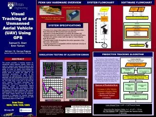
PENN UAV HARDWARE OVERVIEW SYSTEM FLOWCHART SOFTWARE FLOWCHART ¼ Scale Piper J3 Cub UAVs Visual Tracking of an Unmanned Aerial Vehicle (UAV) Using GPS CloudCap Piccolo Onboard Avionics (10 Hz GPS, 100Hz IMU) SYSTEM SPECIFICATIONS • Provide a live visual video output of an object that provides three-dimensional GPS position and velocity data. • Operate in a look-ahead fashion in which the system will anticipate where the vehicle is located in the one-second future. • Interface the camera output with any type of visual display (both IN and OUT) • Provide output visible throughout the entire operation of the UAV. (max. 30 minutes) • Tracking algorithm is compatible with the maximum velocity of a UAV. (20 meters/second) Samuel S. Starr Emir Tumen Advisor: Dr. George Pappas Special Thanks: Ben Grocholsky, Jim Keller SIMULATION TESTING OF ALGORITHM ERROR PREDICTIVE TRACKING ALGORITHM ABSTRACT The Predictive Tracking Algorithm was originally derived using vector theory. While this approach could have worked, it proved unnecessarily complex. An alternative was a geocentric approach, which proved to be too sensitive to any changes in latitude and longitude. The simple geometric approach adopted eliminates substantial sensitivity errors, but is limited in that it works best in close range and only once GPS is converted to UTM. It is the conversion to UTM that allows any geometric algorithm to work precisely. The Look Ahead Time can be adjusted to predict the position of the moving object within the delay time. The project provides a tracking system for Unmanned Aerial Vehicles (UAVs), which are used for research and security purposes and require real time control. Giving the camera the ability to follow an object, and limiting the margin of error in the visual tracking output, the project aims to satisfy the need of an automated surveillance for UAVs at the University of Pennsylvania. In the chosen approach, the GPS information from the UAV is collected and stored in the ground base station PC. The GPS data is then fed to the Pan-Tilt unit’s control PC, which processes this information and converts it to pan and tilt values by using a geometrically based algorithm. Finally, two servomotors which accept these pan and tilt values adjust to point the camera in the UAV’s direction. The current implementation of the system is well suited to any visual output device such as monitors, televisions or webcams for network sharing, and for real-time visual tracking of any GPS transmitting object in a 360° field. • Sources of Predictive Error • Increase in UAV Velocity • Increase in System Delay • Quality of GPS Data • Mechanical System Limitations Demo Times: 1030h, 1100h, 1130h, 1300h Look-Ahead Time = LAT = 1/(k*Freq of Data) Assuming No System Delay: k=1 LAT = 1/Freq For Our System: LAT = Approximate Net System Delay (1 second) Based on the above graphs, and the adjacent chart, the algorithm that minimizes error for system delay and is less sensitive to changes in UAV velocity is when LAT is set equal to the delay on the order of 1 second. Group #6


