Download

1 / 33
410 likes | 871 Vues
The Biot-Savart Law. AP Physics C Montwood High School R. Casao. Biot and Savart recognized that a conductor carrying a steady current produces a force on a magnet.

E N D
The Biot-Savart Law AP Physics C Montwood High School R. Casao
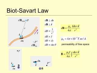
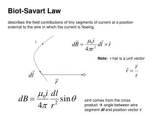
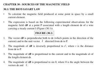
Biot and Savart recognized that a conductor carrying a steady current produces a force on a magnet. • Biot and Savart produced an equation that gives the magnetic field at some point in space in terms of the current that produces the field. • Biot-Savart law says that if a wire carries a steady current I, the magnetic field dB at some point P associated with an element of conductor length ds has the following properties: • The vector dB is perpendicular to both ds (the direction of the current I) and to the unit vector rhat directed from the element ds to the point P.
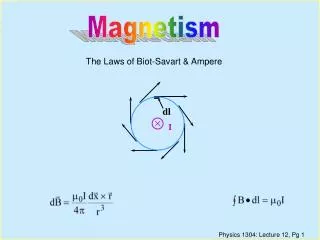
The magnitude of dB is inversely proportional to r2, where r is the distance from the element ds to the point P. • The magnitude of dB is proportional to the current I and to the length ds of the element. • The magnitude of dB is proportional to sin q, where q is the angle between the vectors ds and rhat. • Biot-Savart law:
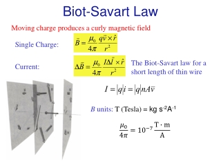
mo is a constant called the permeability of free space; mo =4· x 10-7 Wb/A·m (T·m/A) • Biot-Savart law gives the magnetic field at a point for only a small element of the conductor ds. • To determine the total magnetic field B at some point due to a conductor of specified size, we must add up every contribution from all elements ds that make up the conductor (integrate)!
The direction of the magnetic field due to a current carrying element is perpendicular to both the current element ds and the radius vector rhat. • The right hand rule can be used to determine the direction of the magnetic field around the current carrying conductor: • Thumb of the right hand in the direction of the current. • Fingers of the right hand curl around the wire in the direction of the magnetic field at that point.
Magnetic Field of a Thin Straight Conductor • Consider a thin, straight wire carrying a constant current I along the x axis. To determine the total magnetic field B at the point P at a distance a from the wire:
Use the right hand rule to determine that the direction of the magnetic field produced by the conductor at point P is directed out of the page. • This is also verified using the vector cross product (ds x rhat): fingers of right hand in direction of ds; point palm in direction of rhat (curl fingers from ds to rhat); thumb points in direction of magnetic field B. • The cross product (ds x rhat) = ds·rhat·sin q; rhat is a unit vector and the magnitude of a unit vector = 1. • (ds x rhat) = ds·rhat·sin q = ds·sin q
Each length of the conductor ds is also a small length along the x axis, dx. • Each element of length ds is a distance r from P and a distance x from the midpoint of the conductor O. The angle q will also change as r and x change. • The values for r, x, and q will change for each different element of length ds. • Let ds = dx, then ds·sin q becomes dx·sin q. • The contribution to the total magnetic field at point P from each element of the conductor ds is:
The total magnetic field B at point P can be determined by integrating from one end of the conductor to the other end of the conductor. • The distance a from the midpoint of the conductor O to the point P remains constant. • Express r in terms of a and x. • Express sin q in terms of a and r.
For an infinitely long wire: • From the table of integrals:
For a conductor with a finite length: • From the table of integrals:
When the angles are provided: • express r in terms of a and the angle q: • Because angles are involved, we need to change dx to dq: - Take the derivative of x:
To determine the magnitude of the magnetic field B, integrate:
The magnetic field lines are concentric circles that surround the wire in a plane perpendicular to the wire. • The magnitude of B is constant on any circle of radius a. • The magnitude of the magnetic field B is proportional to the current and decreases as the distance from the wire increases.
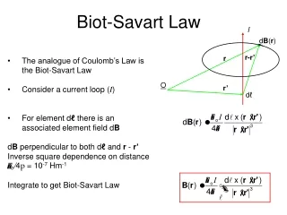
Magnetic Field of a Current Loop • To determine the magnetic field B at the point O for the current loop shown:
The magnetic field at point O due to the straight segments AA' and CC' is zero because ds is parallel to rhat along path AA' and ds is antiparallel to rhat along path CC'. • For the curved portion of the conductor from A to C, divide this into small elements of length ds. • Each element of length ds is the same distance R away from point O.
Each element of length ds contributes equally to the total magnetic field B at point O. • The direction of the magnetic field B at point O is down into the page. • At every point from A to C, ds is perpendicular to rhat, therefore: • Integrate from A to C:
Pull the constant R out in front of the integral and integrate from A to C: • The distance s is the arc length from A to C; arc length s = R·. Revising the equation:
Magnetic Field on the Axis of a Circular Current Loop • Consider a circular loop of wire of radius R in the yz plane and carrying a steady current I:
To determine the magnetic field B at a point P on the axis a distance x from the center of the loop: • Divide the current loop into small elements of length ds. • Each element of length ds is the same distance r to point P on the x axis. • Each element of length ds contributes equally to the total magnetic field B at point P.
Express r in terms of R and x: • Each element of length ds is perpendicular to the unit vector rhat from ds to point P. • Substituting into the integral equation:
Notice that the direction of the magnetic field contribution dB from element of length ds is at an angle q with the x axis.
At point P, the magnetic field contribution from each element of length ds can be resolved into an x component (dBx) and a y component (dBy). • The dBy component for the magnetic field from an element of length ds on one side of the ring is equal in magnitude but opposite in direction to the dBy component for the magnetic field produced by the element of length ds on the opposite side of the ring (180º away). These dBy components cancel each other.
The net magnetic field B at point P is the sum of the dBx components for the elements of length ds. • The direction of the net magnetic field is along the x axis and directed away from the circular loop.
Express R2 + x2 in terms of an angle q: • Substituting into the integral equation:
Pull the constants out in front of the integral: • The sum of the elements of length ds around the closed current loop is the circumference of the current loop; s = 2··R
To determine the magnetic field strength B at the center of the current loop, set x = 0:
For large distances along the x axis from the current loop, where x is very large in comparison to R:
The magnetic dipole m of the loop is the product of the current I and the area A of the loop: m = I··R2