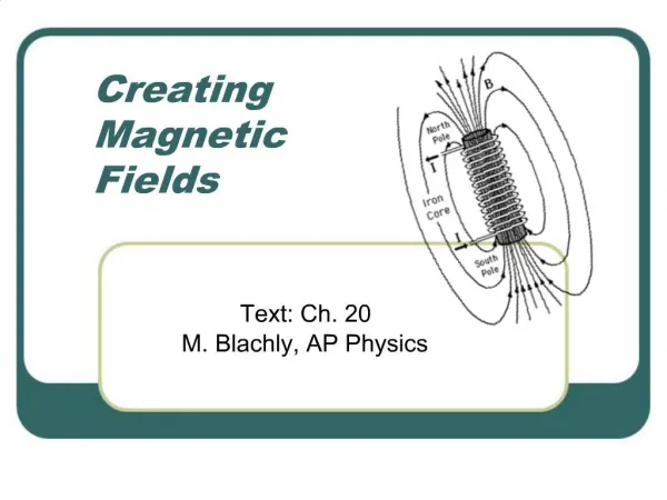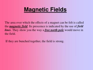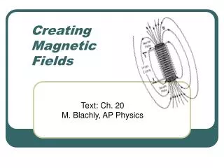
Creating magnetic fields
Creating magnetic fields. Gravitational fields acted on masses, and masses set up gravitational fields: F gravity = mg where g = GM/r 2 Electric fields acted on charges, and charges set up electric fields: F electric = qE where E = kQ/r 2

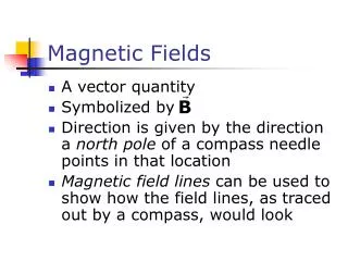
Creating magnetic fields
E N D
Presentation Transcript
Creating magnetic fields Gravitational fields acted on masses, and masses set up gravitational fields: Fgravity = mg where g = GM/r2 Electric fields acted on charges, and charges set up electric fields: Felectric = qE where E = kQ/r2 Magnetic fields acted on moving charges; do moving charges set up magnetic fields?
Creating Magnetic Fields Magnetic fields acted on moving charges; do moving charges set up magnetic fields? YES!From the gravitational and electric cases, we can guess that we will need: a constant that describes the strength similar to G and k; an inverse square relationship with distance (1/r2); and a dependence on what is acted upon (like m and q) - in this case, qv.
Creating Magnetic Fields But we also have the right hand rule in the magnetic force equation, and we’ll need a right hand rule in the field generating equation also:
Magnetic Fields B = (mo/4p) q v sin(qvr) / r2 direction: right hand rule thumb = hand x fingers Point your handin the direction of v, curl you fingers in the direction of r, and the field, B will be in the direction of your thumb; if the charge is negative, the field direction is opposite that of your thumb.
Magnetic Constant The constant (mo/4p) is a seemingly strange way of writing a constant that serves the same purpose as G and k, but that is exactly what it does. The value: (mo/4p) = 1 x 10⁻⁷ T*m*sec/Coul (or 1 x 10⁻⁷ T*m/Amp). In fact, the constant k is sometimes written as: k = 1/(4peo). [In both cases, the sub zero on m and e indicates the field is in vacuum.]
4p ? Why does the combination of 4p enter into the constant? Consider the field idea where the mass, charge, or in this case the moving charge, sets up the field by throwing out field particles. The density of these field particles, and hence the strength of the field, depends on the number of field particles (a constant) and the area they are going through. This area is that of a sphere: 4pr2. Thus the 4p really goes with the r2 in the denominator: B = mo q v sin(qvr) / (4p r2)
Creating Magnetic Fields A single moving charge does create a magnetic field in the space around it, but since both the charge and the constant are very small, we usually don’t have to worry about these effects. But if we have a series of charges moving (which means a current), then we can generate an appreciable magnetic field.
Currents and Magnetic Fields A moving charge (qv) actually can be thought of as a current over a small length: qv = q(DL/Dt) = (DQ/Dt)DL = I DL , so that we have for each small length: B = (mo/4p) I DL sin(qIr) / r2 with direction: thumb(field) = hand(current) x fingers(radius).
General Case For the current over a complete circuit, the field produced at any particular point in space will depend on where the point is and the shape of the circuit. B = (mo I/4p) dL sin(qIr) / r2 where both qIr and r depend on L(that is, they depend on which dL we are at in the sum). Keep in mind that the magnetic field is a vector, so we need to use the RHR and consider components!
Field at the Center of a Loop B = (mo I/4p) dL sin(qIr) / r2 At the center of a circle of current, r = R = constant, and qIL = 90o = constant. Note: all elements will give a field out of the loop! Thus the integral is trivial and we have: Bat center of circle = (mo I/4p)* (2pR)(1) / R2 = mo I/ 2R . If we have several turns in the wire, each RI turn contributes: B = moNI/ 2R .
Field at the Center of a Loop B = moNI/ 2R Note that this field depends on the current (both N andI) and the shape (R). [Note that the only parameter associated with a circle is R.] It has the magnetic constant(mo) in it as well. Only the 2 in the formula can’t be immediately guessed at. Note also that it has the mo and I in the numerator, and it has a distance in the denominator. This should happen for all the different geometries.
Example What is the field strength at the center of a loop that has 5 Amps running through 300 turns, where the radius of the loop is 6 cm? Bat center of loop = mo N I / 2R B = (4p x 10-7 T*m/A) * 300 * 5A / (2*.06m) = .0157 T = 157 Gauss.
Field on axis of circular loop What is the magnetic field on axis but not at the center of a circular loop of current? Using the RHR, the magnetic field due to the element on the right (current going into the page) is up and right as shown on the diagram. B The horizontal field will cancel ar in pairs, but the vertical R components will add! I
Field on axis of circular loop By = B cos(q) where the red dot indicates the angle q on the diagram. Again from the diagram we can see that cos (q) = R/r. From B = (mo I/4p) dL sin(qIr) / r2 with r = constant and qIr= 90o B we have: By= cos(q)*(mo I/4p)*(2pR)(1)/r2 ar = mo IR2 / 2r3 R where r = [a2 + R2]1/2 .I
Field on axis of circular loop Bon axis= mo IR2 / 2r3 Note here also that there is a mo and I in the numerator, and an inverse distance. The geometry depends on both R and r, and both parameters are included in the formula. Note that as a becomes small, r approaches R, and B approaches the result we had for the field at the center of the coil: Bloop = mo I / 2R.
Field off-axis B = (mo I/4p) dL sin(qIr) / r2 Note that if we try to find the field off-axis, both qIr and r no longer remain constant, and hence the integral becomes very hard to integrate!
Magnetic Field due to a current in a straight wire Let’s now consider the magnetic field at some point (x)a distance aabove a current, I, in a straight wire. We start with the Biot-Savart Law: B = (mo I/4p) dL sin(qIr) / r2. By the RHR,the direction of B is out of the screen.x ra I
Magnetic Field due to a current in a straight wire B = (mo I/4p) dL sin(qIr) / r2. From the diagram, we see that sin(qIr) = a/r . We see that both qIr and r depend on which dL we are at. Thus the integral is not trivial, but it does look like one we have done before! x ra -x I
Magnetic Field due to a current in a straight wire B = (mo I/4p) dL sin(qIr) / r2. B = (mo I/4p) xLxRdx (a/r) / r2 where r = [x2 + a2]1/2 . Using the same trick we did before for this integral (method of substitution), we get: x ra -x I
Magnetic Field due to a current in a straight wire Bshort wire = (mo I/4pa)*[cos(qL) - cos(qR)] . For a long wire (a « -xL, a « xR) this reduces to: Blong wire = (mo I/2pa). From the cylindrical symmetry of the wire, we see that the magnetic field is directed around the wire . Note that we again have mo and I in the numerator, and an inverse distance (1/a).
Magnetic Field due to a current in a straight wire Bshort wire = (mo I/4pa)*[cos(qL) - cos(qR)] . Blong wire = (mo I/2pa). For a long wire, the only geometric parameter is a, the distance the point is from the wire. For a short wire, both the length and distance to the wire are contained in the angles qL and qR.
Shortcut RHR rule #1 For the case of a circular loop of wire, the magnetic field went straight through the center. If you curl your right hand fingers in the direction of the current around the loop, your thumb points in the direction of the field through the center of the loop.
Shortcut RHR rule #2 For the case of the straight wire, if you point your right hand thumb in the direction of the straight current, your fingers will curl around in the direction of the circular magnetic field around the wire. Warning: make sure you use your right hand when doing these RHR shortcuts!
Computer Homework There is a computer homework assignment, Vol. 4, #2, on Magnetic Fields that will give you practice with calculating the magnetic fields due to different current geometries.
The Solenoid The solenoid is an important special case for creating magnetic fields. A solenoid is a coil of wire that is wrapped around a cylinder rather than around a circle. It has elements of both the circular loop and the straight wire. It can be solved the straight-forward way, but there is an easier (but trickier) way - we’ll talk about this easier way next.
Gauss’ Law for Magnetism Recall from Part I, Gauss’ Law for Electricity: closed area E dA = 4pkQenclosed. This looked like a hard way to solve for E (since E is inside the integral), but using symmetry it sometimes turns out easy. For magnetism, we cannot separate poles, therefore we cannot enclose any poles. This means that we have: closed area B dA = 0.
Another Law Recall from Part I that Electric Fields started on positive charges and went towards negative charges. For magnetic fields, however, the magnetic fields went around currents. This leads to: closed loop B dL = (constant) * Iencircled. Again, this looks like it will be hard to solve for B (since it is inside the integral), but we’ll see that for some symmetric results, it turns out to be simple.
Ampere’s Law closed loop B dL = (constant) * Iencircled. To determine the constant, we use something we already know: the field due to a long straight wire: B = moI/2pa . Due to the symmetry of the wire, the integral is easy to do and gives: (moI/2pa) * 2pa = constant * I . Thus the constant is simply mo . Thus Ampere’s Law is: closed loop B dL = mo Iencircled.
Back to the solenoid closed loop B dL = mo Iencircled. In using Ampere’s Law, we need to specify a particular closed loop(just as we needed to specify a particular closed area in using Gauss’ Law for Electric Fields).I coming out of page Let’s first consider generally how the field should look: I going into page
The Solenoid Inside the solenoid, the field should be in the same direction as for a circular coil: bend your fingers around in the direction of the circular current, and your thumb will point in the direction of the field: Binside
Inside the Solenoid If we choosea Binside rectangular loop inside the solenoid and go around this loop in a CCW sense, then Ampere’s Law closed loop B dL = mo Iencircledindicates that, since no current is encircled by our rectangle (Iencircled = 0), and since the up and down lengths are to the field, the field near the top and the field in the middle must be the same!
Outside the solenoid This means that the field inside the solenoid is constant(just like the Electric Field was constant between parallel plates). The same argument applies for outside the solenoid, and since we know the field very far away from the long solenoid should be zero, the field near the solenoid (but outside of it) should also be near zero(again like the E field outside of the parallel plates).
Value of Field Inside To find the field inside Binside we choose a rectangular loop halfoutside and half inside. Since the field is to the field on the up and down sides, and since the field is zero on the top, we have: Binside L = mo N I where N is the number of loops in the rectangle of length L.
B inside solenoid Binside L = mo N I becomes when we move the L over and define n = N/L: Binside-long = mo n I . This holds for a very long solenoid. If we do this exactly for a shorter solenoid, we get: Binside-short = ½mo n I [cos(qR) - cos(qL)] . As the diameter of the solenoid becomes small compared to its length, qR 0o and qL 180o giving the long result (see next slide for diagram showing angles).
Solenoid a = R = Diameter/2 xxRwhere xR-xL=L = qR a = R = Diameter/2 x-xL where xR-xL=L = qL (Note: For this position, xL < 0.)
Solenoid Binside-long = mo n I Binside-short = ½mo n I [cos(qR) - cos(qL)] Note that in both cases, we have mo and I in the numerator. But where is the inverse distance?
Solenoid Binside-long = mo n I Binside-short = ½mo n I [cos(qR) - cos(qL)] Note that in both cases, we have mo and I in the numerator. But where is the inverse distance?It is inside the n (n = N/L)! Note that the radius for a long solenoid doesn’t matter. For a short solenoid, the radius and length are both involved in the angles qR and qL.
Force between Currents Masses create gravitational fields that act on other masses, so masses act on other masses. Charges create electric fields that act on other charges, so charges act on other charges. How about currents? Does the mass in one wire affect another wire? Does the charge in one wire affect another wire? Does the current in one wire affect another wire?
Forces between wires Does the mass in one wire affect another wire? Yes, but the amount is insignificant. Does the charge in one wire affect another wire? Normally wires are not charged, so they normally do not affect another wire via this way. Even when they carry current, the current leaving the wire equals the current entering the wire. This normally leaves the wire uncharged even when current is flowing through it!
Forces between currents The current in one wire does set up a magnetic field in the area around the wire, and this magnetic field will act on another current in a neighboring wire and possibly exert a force. Generally, though, this is a small force and a very hard calculation, since the magnetic field will vary across the other wire.
Example I1 = 0.5 Amps What is the force on the I2 = 15 Amps rectangular circuit due to the presence of the 8 cm current in the long wire direction & magnitude? 4 cm 7 cm
Example I1 = 0.5 Amps By symmetry, the force I2 = 15 Amps on the top and bottom parts cancel. Since the 8 cm left side is closer than right, the force on the 4 cm left side will “win”. 7 cm
Example I1 = 0.5 Amps By the RHR, the B field I2 = 15 Amps due to the long wire at B1the left side wire is into Fleft8 cm the screen. The force on the left side by the 4 cm RHR is then to the right 7 cm (repulsive).
Example I1 = 0.5 Amps Bleft = moI1 / 2p (.04 m) I2 = 15 Amps = (2 x 10⁻⁷)(0.5)/(.04) T = 2.5 x 10⁻⁶ T Fleft8 cm Fleft= I2 L Bleft Fright = (15)(.08)(2.5 x 10⁻⁶) N 4 cm = 3.0 x 10⁻⁶ Nt left 7 cm Similarly, Fright = 1.71 x 10⁻⁶ Nt. right.
Example I1 = 0.5 AmpsFL=3.0 x 10⁻⁶ Nt left I2 = 15 Amps FR = 1.7 x 10⁻⁶ Nt. rt Fleft8 cm FT = 1.3 x 10⁻⁶ Nt. left Fright 4 cm 7 cm