David Zamora, MS Medical Physicist
280 likes | 494 Vues
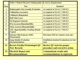
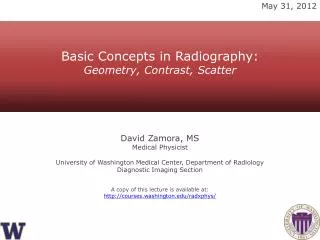
May 31, 2012. Basic Concepts in Radiography: Geometry, Contrast, Scatter. David Zamora, MS Medical Physicist University of Washington Medical Center, Department of Radiology Diagnostic Imaging Section A copy of this lecture is available at: http://courses.washington.edu/radxphys/.

David Zamora, MS Medical Physicist
E N D
Presentation Transcript
May 31, 2012 Basic Concepts in Radiography: Geometry, Contrast, Scatter David Zamora, MS Medical Physicist University of Washington Medical Center, Department of Radiology Diagnostic Imaging Section A copy of this lecture is available at: http://courses.washington.edu/radxphys/
Outline • Geometry • Beam Divergence and Inverse Square Law • Magnification / Penumbra • Radiographic Contrast • Tissue Contrast • Scatter and Scatter Reduction • Basics and Scatter-to-Primary Ratio • Antiscatter Grids
Global Perspective Radiography X-Ray Tube Patient Detector Image Receptor: - A) Analog Detector * Screen-film - B) Digital Detector * Computed Radiography * In-direct Digital * Direct Digital X-ray Source: We (or the system) control: - photon energy (kVp) - # of photons produced (mA) - exposure time (sec). X-ray Interactions in Body: - Photo-electric ϵ Z3/E3 - Compton Scatter ϵ 1/E We take advantage of these photon/tissue interactions to create a usable image. • This is classified as transmission imaging (i.e. photons transmit through patient) • This is a 2D PROJECTION of 3D anatomy! - Anatomical overlay (we lack some spatial information) - SOLUTION: Different views (or a different modality) E – photon energy Z – atomic number
Geometry Beam Divergence 4D 3D 2D Distance = D A 4A 9A 16A L 2L 3L 4L • The x-ray field DIVERGES with increased distance from FS - Field edge (L) increases proportionally with D - Field area (A) increases proportionally with D2 • The same rules hold for rectangular fields, just apply the equation above to each edge • For circular fields, the radius and field size increases by the proportions…
Geometry Inverse Square Law 4D 3D 2D Distance = D Intensity = X X/4 X/9 X/16 • The intensity (X) of the x-ray field decreases with D2: • Ramifications of Inverse Square Law: - Distance can really help or really hurt the situation, use it wisely! • Don’t over-complicate these ‘parameter-as-a-function-of-distance’ relationships – learn the proportionality (i.e. as D or D2), and have an intuition on whether they increase or decrease with distance – then apply an appropriate distance ratio
Geometry Distance Nomenclature Bird’s Eye View OBJECT IMAGE RECEPTOR SOURCE SOD OID SID • Source-to-Image Distance (SID) – distance between x-ray tube focal spot (FS) and whatever detector or image receptor you are using • - Common SIDs: 40” (102 cm) or 72” (183 cm) • Source-to-Object Distance (SOD) – distance between x-ray tube FS and the object you are imaging (patient/phantom) • Object-to-Image Distance (OID) – distance between object (patient) and detector or image receptor • Others you may see: SSD – source-to-skin / SCD – source-to-ion-chamber STTD – source-to-table-top
Geometry ISF – A Cautionary Tale In a rad room, we measure an exposure at 9” above table top for a typical AP L-spine technique (i.e. SID = 40”, 80 kVp, 10 mAs). However, the Washington State exposure limit is referenced to 12” above table top. My measured exposure is 100 mR, what would exposure be at the State’s reference point? SID 40” This is wrong, distance measurements are referenced to the radiation source… STT 37” × × 12” 9” Table 3”
Geometry Demonstration
Geometry Question • Scenario 1: An IR doctor sets the beam collimation to 8” x 10” at the detector surface (SID = 40”), the patient is 15” thick and directly adjacent to the detector. The hospital physicist estimates the radiation dose to the skin as 3.8 Gy (± 30% error). - A) What skin effect(s) are we most likely to observe, and when? - B) What are the dimensions of the skin effect (L x W)? - C) You are offered a rolling lead shield that will cut your own radiation exposure by 80%. Alternatively, you can comfortably reposition at twice the distance. Preference? • A) Transient erythema (< 2 wks) / Possible temporary epilation (2-8 wks) • B) Field Size at skin entry: • Dimension A: L2 = L1 x (D2/D1) = 8” x (25”/40”) = 5” • Dimension B:L2 = L1 x (D2/D1) = 10” x (25”/40”) = 6.25” • Field areas: Adetector = 8” x 10” = 80 in2 | Askin = 5” x 6.25” = 31.25 in2 • C) RollingShield – My exposure is 20% of original intensity. • Distance – My exposure is 1/4th (12/22) or 25% of original intensity.
Geometry Magnification Input Output PROJECTED ON TO… • Beam divergence allows us to have GEOMETRIC MAGNIFICATION (i.e. magnification that comes about due to changes in our geometry – there are other ways also). • By moving the patient toward the tube, the effective input area is smaller, but it is projected onto the same detector area.
Geometry Question • The figure shows a setup for magnification imaging in mammography (breast elevated above the detector surface). What magnification factor do we expect with the shown geometry? a) M = SOD/OID = 35/30 = 1.2 b) M = (SOD+OID)/OID = (35+30)/30 = 2.2 c) M = (SOD+OID)/SOD = (35+30)/35 = 1.9 d) M = (SOD-OID)/OID = (35-30)/30 = 0.2 c.f.: Bushberg, et al, The Essential Physics of Medical Imaging, 2nd Ed, p 211 [cropped]
Geometry Question • The SID of an imaging system for a PA chest exam is 183 cm, there is a 10 cm air gap, and the patient is 20 cm thick. The magnification factor at the posterior surface is _______ and at the anterior surface it is ________. a) 1.06 (post) and 1.20 (ant) b) 1.20 (post) and 1.06 (ant) c) 3.00 (post) and 1.50 (ant) d) 1.50 (post) and 3.00 (ant) 20 10 P A 183 cm
Geometry Geometric Blurring • HOWEVER, we don’t get the benefit of magnification for free! • In reality, the focal spot has a finite dimension that leads to geometric blur - this ‘penumbra’ worsens as we get more magnification. • SOLUTION: Use a smaller focal spot setting • CAVEAT: Smaller focal spots focus heat deposition on anode… IDEAL POINT SOURCE REALITY Finite FS size leads to geometric blur, and this gets worse with MAG c.f.: Bushberg, et al, The Essential Physics of Medical Imaging, 2nd Ed
c.f.: Bushberg, et al, The Essential Physics of Medical Imaging, 2nd Ed, pp 98, 103, 104.
Contrast Basics • Contrast comes about due to differences in the physical properties of whatever you are imaging: • Photon Interactions (Attenuation Properties) • Atomic Mass (Z), density, e- density, thickness, photon energy, etc… Bone Muscle Lung Density [g/cm3] 1.7 1.0 0.1 x 2x Thickness % Transmitted 74% 84% 98% 85% 73% % Transmitted c.f.: Bushberg, et al, The Essential Physics of Medical Imaging, 2nd Ed, p 257. We get a 2-D map of signal OUT of the patient… Graphic adapted from Huda/Stone, Review of Radiologic Physics, 2nd Ed, p 69.
Contrast Basics • Contrast is the difference in some aspect of the signal, and is a consequence of a difference in intensity: • In cases of a uniform material of varying thickness, the difference in thickness (z) drives the contrast. For different materials, the differences in x-ray attenuation properties drive the appearance of contrast (again, this is a function of many things). • Other imaging modalities exploit these and other tissue properties so that we can build contrast in the final image. • Sometimes, we introduce a separate contrast material (e.g. iodine, barium, gad [MR]) to further enhance perceived differences. Note: this is often expressed as a % c.f.: Bushberg, et al, The Essential Physics of Medical Imaging, 2nd Ed, p 257.
Contrast Basics • On a digital radiographic image, a lung lesion is visible (shown in red). Using a circular region of interest (ROI), we measure a digital pixel value (PV) of 5150 on the rib, and a PV of 4850 on the lung (background). What is the percent contrast between the rib and lung ROI? • 0.030 % • 3.0 % • 0.062 % • 6.2 %
Scatter Basics • RECALL: Photons interact with tissue, and have the potential to scatter (i.e. Compton) • In PLANAR radiography, our hope/assumption is that we are actually receiving a planar projection • With scatter, this assumption starts to break down - we lose straight ray paths • Scatter degrades image contrast – degree of scatter commonly described as scatter-to-primary ratio (S/P) – generally speaking, lower S/P is desirable [ f(field size, patient size, etc…) ] c.f.: Bushberg, et al, The Essential Physics of Medical Imaging, 2nd Ed, p 167.
Scatter Scatter Rejection - Grids We insert an ANTISCATTER GRID with the purpose of rejecting scattered photons from our projection… • CONSTRUCTION: attenuating septa (Pb or Ta) and interspaces (Carbon-fiber) aligned to beam • Primary x-rays have a higher probability of passing through and being detected • Grid Ratio: Higher ratio indicates more collimation, and necessitate high patient dose (again, no free lunch) c.f.: [lower] Bushberg, et al, The Essential Physics of Medical Imaging, 2nd Ed, p 169.
Scatter Questions • The number of scattered photons reaching a detector decreases with increasing: a) Field Size b) Patient Thickness c) Peak Kilovoltage (kVp) d) Filtration e) Grid Ratio Higher grid ratios lead to the rejection of more scattered radiation. Scatter increases with increasing field size and patient size. Higher kVp leads to better penetration of the patient overall, more photons available for detection. Increased filtration decreases low energy photons, raises effective kVp.
Scatter Questions • High ratio grids increase all of the following except: a) Required mAs (i.e. number of photons) to maintain image quality b) Image Low-Contrast Resolution c) Patient Dose d) Removal of Scatter e) Screen/film Speed Screen/film speed is a property of the film used, and doesn’t have anything to do with the grid, per se. Options a) – d) all increase with higher grid ratio.
Supplemental Questions • Raphex 2001: Geometric magnification can improve the detection of high contrast objects. The fundamental limitation on useful magnification is: a) Blurring due to focal spot size b) Blurring due to removal of the grid c) H and D curve of the image receptor d) MTF of the image receptor e) Size of the image receptor Penumbra, caused by a finite focal spot, increases with magnification. Eventually this dominates the image. The grid, H&D curve, and size have no effect on magnification. The receptor’s MTF becomes less important as magnification increases.
Supplemental Questions • Raphex 2002: A newly installed bucky radiographic system produces abdominal images that are of acceptable density over the spine and progressively lighter toward both lateral edges of the film. The most likely reason for this finding is improper: a) Collimator tracking b) Focal distance for grid c) Grid ratio d) kVp calibration of the system e) Programming of the AEC system Cut-off is caused because the grid strips no longer “aim” at the focal-spot. Remember that the grid is designed for certain conditions and it must be used as such - otherwise you may end up with image artifact.
Supplemental Questions • Raphex 2003: Low contrast detectability refers to the ability of a system to distinguish: a) A calcified lung nodule b) A non-calcified lung nodule c) Between overlying and underlying tissues d) The size of a small tissue e) Vessels during the arterial phase of a normal angiogram Low contrast detectability represents the ability of a system to reproduce an object whose linear attenuation coefficient does not vary greatly from the surrounding material