‘Realistic’ particle distribution (*) from RCS for MR (analysis)
140 likes | 287 Vues
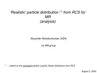
‘Realistic’ particle distribution (*) from RCS for MR (analysis). Alexander Molodozhentsev (KEK) for MR-group. * … based on the corrected particle (July29_Noda) distribution from RCS. August 2, 2005. RCS: 3GeV transverse particle distribution. Noda san’s data: July29_05/181_cor216_30ma

‘Realistic’ particle distribution (*) from RCS for MR (analysis)
E N D
Presentation Transcript
‘Realistic’ particle distribution (*) from RCS for MR(analysis) Alexander Molodozhentsev (KEK) for MR-group * … based on the corrected particle (July29_Noda) distribution from RCS August 2, 2005
RCS: 3GeV transverse particle distribution Noda san’s data: July29_05/181_cor216_30ma … LINAC … 181 MeV … @14670t : energy scaling … Wkin = 3GeV … beam intensity from RCS = 0.6MW at 3 GeV … Particle distribution at the RCS_FOIL location … … 96773 macro particles
RCS: 3GeV transverse particle distribution Twiss parameters at the RCS_FOIL (Noda san) : x = 10.90864 m, y = 10.85614 m x = 1.514302 , y = - 1.604249 Twiss parameters from the distribution analysis: x = 12.427 m, y = 10.916 m x = 1.7189 , y = - 1.6343 x,RMS = 6.886 .mm.mrad y,RMS = 7.889 .mm.mrad
3GeV Beam : Transverse Particle DistributionX-PX plot (RCS_FOIL) Noda san’s data: July29_05/181_cor216_30ma
3GeV Beam : Transverse Particle DistributionY-PY plot (RCS_FOIL) Noda san’s data: July29_05/181_cor216_30ma
3GeV Beam : Transverse Particle DistributionX-Y plot (RCS_FOIL) Noda san’s data: July29_05/181_cor216_30ma
RCS _MR: LINEAR transformation of the transverse particle distribution from RCS_FOIL (p#1) to MR_SCR(p#2) Twiss parameters from the distribution analysis for RCS_FOIL: x = 12.427 m, y = 10.916 m x = 1.7189 , y = - 1.6343 “Lattice” Twiss parameters for MR_SCR: x = 12.890 m, y = 14.160 m x = -1.456 , y = 1.456
MR_SCR: 3GeV Transverse particle distributionX-PX 81 .mm.mrad
MR_SCR: 3GeV Transverse particle distributionY-PY 81 .mm.mrad
3GeV Beam : Transverse Particle DistributionX-Y plot (MR_SCR)
MR_SCR: 3GeV Transverse particle distribution • Emittance analysis of the ‘realistic’ beam from RCS (0.6MW) • > 54 mm.mrad : (H) 1.68% / (V) 0.85% • 99%-emittance: (H) 59.726 / 52.797 mm.mrad • 100%-emittance: (H) 102.475 / 91.161 mm.mrad
Footprint of the beam at the injection energy (MR) Space charge detunning … h = 9 (8 bunches) RCS beam power = 0.6 MW Number of particles per bunch = (3.331014 / 8) * 0.6 Assumption : bunching factor ~ 0.4 ( = 70 degree) ‘Bare’ working point Qx0 = 22.42 / Qy0 = 20.82 NO image forces in chamber !
Footprint of the beam at the injection energy (MR) Parabolic TD (100% emittance=54 mm.mrad) Uniform LD ( = 70 deg) Qx Qx0 Qy Qy0 Qx0 = 22.42 Qy0 = 20.82
Footprint of the beam at the injection energy (MR) “Realistic” TD Uniform LD ( = 70 deg) Qx Qx0 Qy Qy0 Qx0 = 22.42 Qy0 = 20.82