Download
1 / 69
710 likes | 969 Vues
VII Contrasting Techniques From Brightfield to Plas-DIC December 2008. Rudi Rottenfusser. 0 Units. 50 Units. 100 Units. C ONTRAST. 50. 50. 50 Units. 50 – 100 / 50 + 100 = -0.33. 50 – 0 / 50 + 0 = 1. 50 – 50 / 50 + 50 = 0. Illumination Techniques - Overview. Transmitted Light

E N D
VII Contrasting Techniques From Brightfield to Plas-DIC December 2008 Rudi Rottenfusser
0 Units 50 Units 100 Units C ONTRAST 50 50 50 Units 50 – 100 / 50 + 100 = -0.33 50 – 0 / 50 + 0 = 1 50 – 50 / 50 + 50 = 0
Illumination Techniques - Overview Transmitted Light • Brightfield • Oblique • Darkfield • Modulation, Varel Contrast • Phase Contrast • Polarized Light • DIC (Differential Interference Contrast) • Fluorescence - not any more > Epi ! Incident Light • Brightfield • Oblique • Darkfield • Not applicable • Not any more (DIC !) • Polarized Light • DIC (Differential Interference Contrast) • Fluorescence (Epi)
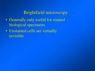
Brightfield • For stained or naturally absorbing samples • True Color Representation • Proper Technique for Measurements • Spectral • Dimensional
d dmin Brightfield Best Resolution when Condenser NA matches Objective NA! Minimum Contrast! Resolution (minimum resolved distance between 2 details): Objective Specimen Condenser
Getting more contrast in the microscope: “Dropping” the condenser Bad Idea! • No more separation of controls for field size and aperture angle • Higher contrast, but at the cost of NA • Scattered light enters the objective • Condenser not in proper position > spherical/chromatic aberrations
Getting more contrast in the microscope: “Stopping down” the condenser (reducing the size of aperture diaphragm) • Increases contrast • Increases depth of field • Reduces resolution Condenser Aperture matches Objective Condenser Aperture stopped down
Effect of Aperture Diaphragm NA Condenser = NA Objective
Paramecium bursaria Condenser diaphragm open Condenser Diaphragm almost closed
Paramecium bursaria Different Staining Techniques Indian Ink Staining Feulgen Staining Silver Staining
Contrasting TechniquesGoing more into details Brightfield Oblique Darkfield Phase Varel Hoffman Pol DIC Plas-DIC
Getting more contrast in the microscope: • Oblique Illumination • (moving the aperture diaphragm sideways) • Increases contrast • Increases depth of field • 3-D effect • Slightly reduces resolution
Required conditions:Illumination Aperture must be larger than objective aperture I.e. direct light must bypass observer Darkfield Low NA Objective Iris Diaphragm High NA Objective
Darkfield Highest contrast Detection of sub-resolution details possible No staining necessary Central Darkfield via “hollow cone” Oblique Darkfield via Illumination from the side Excellent technique to detect traces of contaminants Not useful for Measurements (sizes exaggerated)
Paramecium bursaria Polarized Light Darkfield
Phase Contrast (Frits Zernike 1934) • - “Halo” effect > Reduced resolution • + No staining necessary • + Good Depth of Field • + Easy alignment • + Orientation independent • + Repeatable setup • + Works with plastic dishes • + New positive / negative Phase Contrast
Required Components for Phase Contrast: • Objective with built-in Phase Annulus • Condenser or Slider with Centerable Phase Ring for illumination (Ph0, 1, 2 or 3) Required Adjustment: Superimpose Phase Ring of condenser over (dark) phase plate of objective (after Koehler Illumination)
Illumination bypasses Specimen > no phase shift • Illumination passes through thin part of Specimen > small phase retardation • Illumination passes through thick part of Specimen > larger phase retardation Phase Shifts: Cells have higher n than water. Light moves slower in higher n, consequently resulting in a phase retardation Phase shift depends on n and on thickness of specimen detail
Intermediate Image Phase Contrast Imaging Path Diffraction Orders Non-diffracted wave (shifted by +l/4) -2 -1 0 +1 +2 Phase Plate Non-diffracted wave Diffracted wave (shifted by -l/4) Objective Specimen Condenser Condenser Phase Ring {
Non-diffracted and diffracted light are focused via tube lens into intermediate image and interfere with each other; ¼+¼= ½ wave shift causes destructive interference i.e. Specimen detail appears dark • Affected rays from specimen, expressed by the higher diffraction orders, do not pass through phase ring of objective >¼ wave retarded Tube Lens • Objective Phase Ring a) attenuates the non-diffracted 0th Order b) shifts it ¼ wave forward Objective Specimen Condenser • Illumination from Condenser Phase Ring (“0” Order) > meets phase ring of objective
Positive and negative Phase Contrast in one Objective Objectives: LD Plan-Nefluoar 20x Ph1 Ph2- KorrLD Plan-Neofluar 40x Ph1 Ph2- Korr MDCK cells (dog) R. Nitschke and F. Kotsis, Life Imaging Center, Freiburg Positive Phase Contrast Negative Phase Contrast More Information in Phase Contrast Observation
Paramecium bursaria Brightfield PhaseContrast Condenser diaphragm open
Rhipidodendron Cochliopodium PhaseContrast PhaseContrast
Lyngbya Bacteria PhaseContrast
Thin Phase Object in plastic vessel Varel Contrast Neurons
Varel Contrast (1996 - Zeiss) For unstained (live) specimens Combination of oblique illumination and attenuation of non-diffracted light No “Halo”-effect as in Phase Contrast Complementary technique to Phase (easy switchover) Simulated 3-D image (similar to DIC) Less resolution than DIC Works with plastic dishes
Back Focal Plane of Varel / Phase Objective • Required Components for Varel: • Objective with Varel- and Ph ring • Slider or Condenser with specific Varel 1 or Varel 2 ring sector “Varel” Brightfield / oblique Darkfield Movable Ring Sector (Varel Ring)
Modulation Contrast (Hoffman) • For unstained (live) specimens • Simulated 3-D image (similar to DIC) • No Halo-effect (as in Phase Contrast) • Usable with plastic dishes • Less resolution as DIC • Note: Modulation Contrast Objectives are not recommended for fluorescence; due to potential damage of modulator and uneven illumination
Modulation Contrast 3% transmittance Required Components for Modulation Contrast:Specially Modified Objective (With Built-in Modulator)Modified Condenser with off-axis slit (double slit with polarizer)
Polarized Light • One starts out usually by crossing two polarizers (polarizer and “analyzer”) in a microscope. • The specimen is located between them. • Only birefringent particles (e.g. crystals) become visible, when they are rotated via rotating stage. • Isotropic components will remain dark. • Polarized Light looks sometimes just like Darkfield because edges become visible due to “edge birefringence”.
Polarized Light Analyzer Birefringent Material Polarizer
Polarized Light Analyzer Polarizer Analyzer Birefringent Material Polarizer
Polarized Light Analyzer Analyzer Polarizer Birefringent Material Polarizer
Polarized Light Analyzer Birefringent Material Polarizer
Polarized Light Analyzer Birefringent Material Polarizer
Polarized Light When Polarizers are crossed, only items that rotate the plane of polarization reach the detector. Polarizer 2 (Analyzer) Wave plate adds color Specimen Polarizer 1
BirefringentMaterial Color of sample and background modified by wave plate Background Polarized Light Brightfield Pol + Red I
Required / Recommended Components: • Polarizer (fixed or rotatable) • Analyzer(fixed or rotatable) • Strain-free Condenser and Objective • Rotating, centerable Stage • Wave plate and/or Compensator • Crossline Eyepiece
Birefringence • The numerical difference between the maximum and minimum refractive indices of anisotropic substances. nγ - nα. • Birefringence may be qualitatively expressed as • low (0 - 0.010), • moderate (0.010 – 0.050) • high (>0.050) • extreme (>0.2) • Birefringence may be determined by use of compensators, or estimated through use of a Michel-Lévy Interference Color Chart.
An excellent introduction to this chart is provided at McCrone’s website http://www.modernmicroscopy.com/main.asp?article=15 LOW < 0.010 Moderate 0.010 – 0.050 High > 0.050
3rd Order Red 2nd Order Red 1st Order Red 1st Order Red 2nd Order Red 3rd Order Red
alpha gamma 1st Order Red Plate 550 nm Retardation Sensitive Tint Field of View I/Io Retardation (nm)
Orthoscopy / Conoscopy • Analyzing minerals is based on such morphological and optical features as form, cracks, color, pleochroisms, and their characteristic interference colors. • Orthoscopy and conoscopy are the most important techniques in classical transmitted light polarization microscopy. With their different ways of examining, they provide different options, e.g. in mineral diagnosis in geological microscopy. • In orthoscopy, each pixel corresponds to a dot in the specimen. • In conoscopy, each pixel corresponds to a direction in the specimen. This technique requires the use of the highest objective and condenser aperture possible. • Conoscopy is used when additional information about the specimen is necessary for analysis. It provides interference images that can be seen through the eyepiece and enables differentiation according to 1 or 2 axes and with compensator λ (λ-lamda, Red I), according to 1-axis positive/negative or 2-axis positive/ negative. • A Bertrand lens in the light path makes visible the interference or axial image in the back focal plane of the specimen.
Some Types of Birefringence • Intrinsic or crystalline(Quartz, Calcite, Myosin Filaments, Chromosomes, Keratin, Cellulose Fibers) • Form or Textural(Plasma membranes, Actin filaments, microtubules) • Edge(resulting from diffraction at edges of objects embedded in a medium of different refractive Index) • Strain(resulting from mechanical stress e.g. glass, plastic sheets) • Circular–also known as-Optical Rotation(sugars, amino acids, proteins)
Light as an electromagnetic wave The wave exhibits electric (E) and magnetic (B) fields whose amplitudes oscillate as a sine function over dimensions of space or time. The amplitudes of the electric and magnetic components at a particular instant or location are described as vectors that vibrate in two planes perpendicular to each other and perpendicular to the direction of propagation. At any given time or distance the E and B vectors are equal in phase. For convenience it is common to show only the electric field vector (E vector) of a wave in graphs and diagrams.
y E x E z Ey Ex Polarized Light E