Download
1 / 47
470 likes | 489 Vues
This lecture covers finite state machine design with a hardware approach, exploring Mealy and Moore Machines, edge-triggered flip-flops, state machine analysis, and synthesis. It emphasizes breaking circuits into functional blocks, optimizing logic forms, and identifying hazards in design. Various types of state machines, control conditions, hazards, and design processes are discussed, providing insights into asynchronous vs. synchronous logic and the challenges faced in Mealy Machine design. The importance of output stability in Moore Machines and flip-flop design considerations are highlighted.

E N D
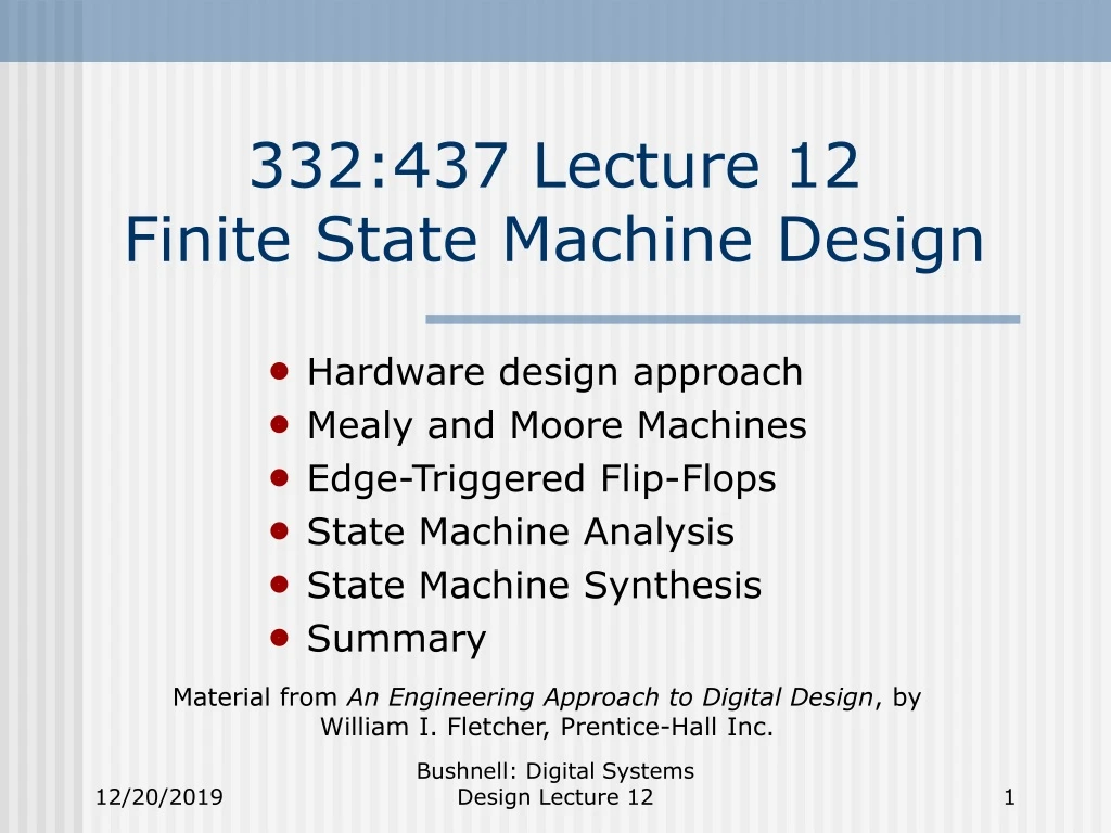
332:437 Lecture 12Finite State Machine Design • Hardware design approach • Mealy and Moore Machines • Edge-Triggered Flip-Flops • State Machine Analysis • State Machine Synthesis • Summary Material from An Engineering Approach to Digital Design, by William I. Fletcher, Prentice-Hall Inc. Bushnell: Digital Systems Design Lecture 12
Suggested Hardware Design Approach • Break circuit design into multiple functional blocks • Optimize each block into a 2-level or multi-level logic form (K-map, Variable-entered map, Synopsys, etc.) • Check for acceptable propagation delay in the system, and go back to Steps 1 and 2 for redesign, if necessary • Use a redundant logic identification to find unnecessary logic and remove it Bushnell: Digital Systems Design Lecture 12
State Machine Design Sequential logic, circuits, or machines: • Have internal memory • Types: • Synchronous (clocked) – memory elements controlled by an external signal – can change only at specific times • Asynchronous – less frequently used but more interesting – memory elements change state whenever 1 or more inputs change – no clock Bushnell: Digital Systems Design Lecture 12
State Machine Design • VERY IMPORTANT: Control conditions under which state changes • Otherwise single input change causes many state changes, due to relative logic delays • Asynchronous Logic: • Faster than synchronous for small circuits • Slower than synchronous for large circuits • REASON: Vastly more logic is required due to absence of CLOCK Bushnell: Digital Systems Design Lecture 12
Mealy Machines Circuit Outputs (present) • Mealy Machine X Z Present Inputs Output Decoder Z = f (X, St) Next State Decoder St Next State Present State Memory Devices Or State St+1 = g (X, St) Clock Bushnell: Digital Systems Design Lecture 12
Moore Machines Circuit Outputs (present) Z Output Decoder Z = f (St) Present Inputs X Next State Decoder St Next State Present State Memory Devices Or State St+1 = g (X, St) Clock Bushnell: Digital Systems Design Lecture 12
Mealy Machines • Nasty to design reliably and debug • WHY? • Real circuits have hazards: • Undesirable: You expect c to be 0, and run it as input to a flip-flop which catches the short logic 1 pulse on c (called one’s catching) • Flip-flop gets set, but you expected it to be cleared 0 1 a c 0 0 1 0 b a b hazard c Bushnell: Digital Systems Design Lecture 12
Hazards • Unavoidable • Different signals have different propagation delays • Different paths through circuit • Different logic gates have different delay times – determined by: • Gate type • Number of inputs • Mealy machines do not filter out hazards, from inputs to outputs • WHY? Output decoder is a function of inputs as well as of state Bushnell: Digital Systems Design Lecture 12
Hazards Propagating Through Output Decoder • Output decoder: • Timing diagram: Xi Zk Sjt Clock Xi Sjt Zk Bushnell: Digital Systems Design Lecture 12
Moore Machine • Output is stable: • Filters out hazards in primary outputs, since they cannot propagate from inputs to outputs • Rule: Never design a Mealy Machine unless you really have to • Unfortunately, you often have to do it to satisfy the circuit functional specification Bushnell: Digital Systems Design Lecture 12
State Machine Design Process • Identify State Variables S • Identify Output Decoder & Next State Decoder • Build State Transition Diagram • Minimize States • Choose appropriate type of flip-flops • Choose State Assignment • Assignment of binary codes to machine states • Design next state decoder & output decoder – use combinational logic structured design methods – K-maps, Variable-Entered Map, Verilog Bushnell: Digital Systems Design Lecture 12
1/0 S1 S2 0/0 0/0 Present Input X/Z 1/0 Present State S1 S2 S3 0 S1/0 S1/0 S1/1 1 S2/0 S3/0 S3/0 0/1 S3 1/0 Mealy Machine Sequence Detector Recognizing 1102 • Double circle shows reset state X/Z Bushnell: Digital Systems Design Lecture 12
Present Output Present Input S1/0 0 1 Present State S1 S2 S3 S4 0 S1 S1 S4 S1 1 S2 S3 S3 S2 Z 0 0 0 1 0 0 1 S2/0 S4/1 0 1 S3/0 1 Moore Machine Sequence Detector Recognizing 1102 • Pay for better behavior of Moore machine with extra flip-flop Bushnell: Digital Systems Design Lecture 12
/S Q 00 for /R & /S not allowed Q /R Master latch Slave latch R Q S 1 5 3 7 Q 11 for R & S not allowed Q S 4 8 Q 2 6 R CP Flip-Flops • Cross-coupled NOR/NAND latches • Clocked Master-Slave Flip-Flop (Pulse or level-triggered) Bushnell: Digital Systems Design Lecture 12
CP S Setup Hold R Enable 1 & 2 Disable 1 & 2 Enable 5 & 6 Disable 5 & 6 One’s Catching Problem • Timing Diagram shows problem • Master starts oscillating • If too close to clock falling edge, Slave might record a 0, not a 1 Bushnell: Digital Systems Design Lecture 12
Edge-Triggered Flip-Flop • Sensitive only to input changes around rising clock edge (positive edge-triggered) • Setup and Hold times • Less likely to catch a 0 or 1 • Characteristic Table: Qt 0 1 0 1 D 0 0 1 1 Qt+1 0 0 1 1 Bushnell: Digital Systems Design Lecture 12
1 0 Forces S & R to 1 C D = 1 D = 0 Forces B to 1 A to 0 Forces B to 0 A to 1 C 0 1 C 0 1 Forces R High S Low Sets FF Forces S High R Low Resets FF Edge-Triggered Flip-Flop State Transition Diagram Bushnell: Digital Systems Design Lecture 12
A /S Q C /R Q D B Edge-Triggered Flip-Flop Logic Circuit Bushnell: Digital Systems Design Lecture 12
Sequential Circuit Analysis • Identify inputs (X’s), outputs (Z’s), coded states (Y’s) • Obtain output equations Z = F (X, Y) • Obtain Flip-Flop excitation equations Di = Gi (X, Y) • Construct Excitation Table from excitation equations for all possible output states • Construct Next State Table from Excitation Table • Merge output functions to Next State Table • Form Coded State Transition Table • Construct State Transition Table from Coded State Transition Table • Construct State Transition Diagram Bushnell: Digital Systems Design Lecture 12
z 5 x 1 y1 y2 C y1 y1 2 y2 x 3 y2 y1 C J2 Q2 J1 Q1 x y2 4 y1 K2 Q2 K1 Q1 CLK Example – Mealy Machine Bushnell: Digital Systems Design Lecture 12
Analysis • z is output y1 and y2 are state variables – maximum of 4 states X = [x = 0, x = 1] Z = [z = 0, z = 1] Y = [y1y2 = 00, 01, 10, 11] • Output Equations z = xy1 • Flip-Flop Excitation Equations J1 = x y2 J2 = x y1 K1 = y1 + y2 K2 = x y1 Bushnell: Digital Systems Design Lecture 12
x y1y2 00 01 11 10 0 00,01,0 11,01,0 11,10,0 01,10,0 1 10,10,0 01,10,0 01,11,1 11,11,1 Analysis (continued) • Evaluate J1, K1, J2, K2 under all possible inputs • Flip-Flop Excitation Table J1K1,J2K2,z Bushnell: Digital Systems Design Lecture 12
x y1y2 00 01 11 10 0 00 10 01 01 1 11 01 00 01 Analysis (continued) • Apply JK FF Characteristic Table to Flip-Flop Excitation Table to get Next State Table Bushnell: Digital Systems Design Lecture 12
x/z y1y2 00 01 11 10 0 00/0 10/0 01/0 01/0 1 11/0 01/0 00/1 01/1 Analysis (continued) • Create Coded State Transition Table • Merge in Present Output Bushnell: Digital Systems Design Lecture 12
x/z y1y2 00 01 11 10 State a b c d 0 a/0 d/0 b/0 b/0 1 c/0 b/0 a/1 b/1 Analysis (continued) • Create State Transition Table • Name the states – each distinct combination of y1y2 Bushnell: Digital Systems Design Lecture 12
1/0 b 0/0 1/0 0/0 a c 0/0 1/1 1/1 d 0/0 Analysis (concluded) • Use State Transition Table to create State Transition Diagram State b – recognized 10 1’s 01 O/P high State a – recognized 0’s 11 Bushnell: Digital Systems Design Lecture 12
State Machine Synthesis • Same steps as analysis, but in reverse • Write accurate word description of the problem. “Build a machine that will produce 1 on the output z when 4+ consecutive 1’s occur on x after at least one 0 input has occurred.” • Form State Transition Table • State Reduction If 2 states a & b have same output sequence when started in a & b for any input sequence, they are equivalent states • Outputs & next states must be same Bushnell: Digital Systems Design Lecture 12
Synthesis (continued) • Make state assignment • Problems: • No known general procedure gives minimal cost • Make all unused states transition to idle state under all input conditions • Avoids state trapping in illegal state • Make Coded State Transition Table • Choose Flip-Flop Type • For SSI, MSI, LSI JK works best – simplifies Next State & Output decoders • For VLSI and ULSI, Use D flip-flops Bushnell: Digital Systems Design Lecture 12
Synthesis (concluded) • Obtain Flip-Flop Excitation Tables • Complete & Minimize Flip-Flop Excitation Equations • Complete & Minimize Flip-Flop Output Equations • Complete Sequential Circuit Design Bushnell: Digital Systems Design Lecture 12
0/0 0/0 0/0 1/0 1/0 1/0 1/1 1 2 3 4 5 6 0/0 1/0 0/0 0/0 1/1 0/0 7 1/0 Example • Produce 1 on z output after 4+ consecutive 1’s on input x after at least one 0 input on x • Assume that x is synchronized with the clock • State Diagram – Mealy Machine Bushnell: Digital Systems Design Lecture 12
x 1 7/0 3/0 4/0 5/0 6/1 6/1 7/0 State 1 2 3 4 5 6 7 0 2/0 2/0 2/0 2/0 2/0 2/0 2/0 Final State Transition Table Bushnell: Digital Systems Design Lecture 12
x 1 1/0 3/0 4/0 5/0 5/1 State 1 2 3 4 5 0 2/0 2/0 2/0 2/0 2/0 State Reduction • # Flip-Flops = log2 (# states) • States 5 & 6 are equivalent • States 1 & 7 are equivalent • Reduced State Transition Table Bushnell: Digital Systems Design Lecture 12
y2 0 0 1 1 1 y1 0 0 0 0 1 y3 0 1 1 0 0 State 1 2 3 4 5 State Assignment • Assign binary codes to state names Bushnell: Digital Systems Design Lecture 12
x y1 0 0 0 0 1 1 1 1 y2 0 0 1 1 1 1 0 0 y3 0 1 1 0 0 1 1 0 0 001/0 001/0 001/0 001/0 001/0 XXX/X XXX/X XXX/X 1 000/0 011/0 010/0 110/0 110/1 XXX/X XXX/X XXX/X State 1 2 3 4 5 Coded State Transition Table Bushnell: Digital Systems Design Lecture 12
Qt 0 0 1 1 Qt+1 0 1 0 1 D 0 1 0 1 y1x y2y3 00 01 11 10 00 0 0 0 0 01 0 0 0 0 10 XXX0 11 XXX 1 Flip-Flop Selection and Output Decoder • Select D flip-flops • Flip-Flop Excitation Table • Output Karnaugh Map • z = x y1 Bushnell: Digital Systems Design Lecture 12
y1x y2y3 00 01 11 10 y1x y2y3 00 01 11 10 D1 D2 00 0 0 0 0 01 0 0 0 1 10 XXX0 00 0 0 0 0 01 0 1 1 1 10 XXX0 11 XXX 1 11 XXX 1 y1x y2y3 00 01 11 10 D3 00 1 1 1 1 01 0 1 0 0 10 XXX1 11 XXX 0 K-Maps for Next State Decoder • D1 = x y2 y3 • D2 = x y3 + x y2 = x (y2 + y3) • D3 = x + y2 y3 Bushnell: Digital Systems Design Lecture 12
z x y1 y2 y3 y1 x y2 y2 y3 D2 D1 D3 Q3 Q2 Q1 y2 x y3 C C C Q3 Q2 Q1 y2 y3 y3 CLK Final Machine Bushnell: Digital Systems Design Lecture 12
Problems • No way to initialize machine – comes up in randomly-chosen state in real hardware • SOLUTION: Add reset line and initialize all flip-flops • If machine fails during operation & goes into undefined state, no guarantee that it will ever reenter a legal state • SOLUTION: Design next state decoder so that a path always exists from undefined states to legal states Bushnell: Digital Systems Design Lecture 12
Problems (continued) • Sequential Machines cannot be tested • SOLUTIONS: • Choose state assignment to allow testing • Add test mode to guarantee initializing sequence for all states • SCAN design – in test mode, all flip-flops become a giant shift register • Can shift in and shift out states • Partial SCAN Design – Apply Method 3 only to selected flip-flops Bushnell: Digital Systems Design Lecture 12
0/0 0/0 1/0 1/0 1/0 1 2 3 4 5 0/0 0/0 0/0 1/0 1/1 X/X X/X X/X 6 7 8 Corrected State Machine Design Bushnell: Digital Systems Design Lecture 12
x State 1 2 3 4 5 6 7 8 0 2/0 2/0 2/0 2/0 2/0 1/0 1/0 1/0 1 1/0 3/0 4/0 5/0 5/1 1/0 1/0 1/0 Corrected State Transition Table Bushnell: Digital Systems Design Lecture 12
x y1 0 0 0 0 1 1 1 1 y2 0 0 1 1 1 0 0 1 y3 0 1 1 0 0 0 1 1 0 001/0 001/0 001/0 001/0 001/0 000/0 000/0 000/0 1 000/0 011/0 010/0 110/0 110/1 000/0 000/0 000/0 State 1 2 3 4 5 6 7 8 Improved Coded State Transition Table Bushnell: Digital Systems Design Lecture 12
y1x y2y3 00 01 11 10 y1x y2y3 00 01 11 10 D1 D2 00 0 0 0 0 01 0 0 0 1 10 0000 00 0 0 0 0 01 0 1 1 1 10 0000 11 000 1 11 000 1 y1x y2y3 00 01 11 10 D3 z 00 1 1 1 1 01 0 1 0 0 10 0001 00 0 0 0 0 01 0 0 0 0 10 0000 11 000 0 11 000 1 Changed Karnaugh Maps y1x y2y3 00 01 11 10 Bushnell: Digital Systems Design Lecture 12
Changed Equations • D1 = x y2 y3 • D2 = x y2 y3 + x y1 y3 • D3 = x y1 + y1 y2 y3 + x y2 y3 • z = x y1 y2 y3 Bushnell: Digital Systems Design Lecture 12
z x y1 y2 y3 y3 y1 y2 x y1 y3 y2 D1 D3 D2 Q2 Q3 Q1 x y3 y1 C C C Q3 Q2 Q1 y2 y3 CLK x reset y2 y3 Improved Logic Diagram Bushnell: Digital Systems Design Lecture 12
Implementation Comparisons New Implementation 1 4-input AND 4 3-input AND 1 2-input AND 1 3-input OR 2 2-input OR 1 Inverter Old Implementation 1 3-input AND 3 2-input AND 2 2-input OR 1 Inverter Bushnell: Digital Systems Design Lecture 12
Summary • Hardware design approach • Mealy and Moore Machines • Edge-Triggered Flip-Flops • State Machine Analysis • State Machine Synthesis Bushnell: Digital Systems Design Lecture 12