The OSI Model
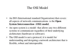
The OSI Model. History of OSI Model. ISO began developing the OSI model in 1977. It is widely accepted as a model for understanding network communication The OSI model is nothing tangible; it is simply a conceptual framework that can be used to understand network communication.


The OSI Model
E N D
Presentation Transcript
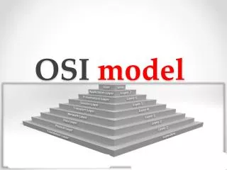
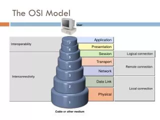
History of OSI Model • ISO began developing the OSI model in 1977. • It is widely accepted as a model for understanding network communication • The OSI model is nothing tangible; it is simply a conceptual framework that can be used to understand network communication. • The OSI model defines seven layers and specifies what tasks need to be done at each layer.
Protocol Stacks • A protocol stack is a group of protocols arranged on top of each other as part of a communication process. • Each layer of the OSI model has different protocols associated with it. • An example of a protocol stack is TCP/IP • Each layer in the protocol stack receives services from the layer below it and provides services to the layer above it. • For two different computers to communicate, the same protocol stack must be running on each computer.
Communication Between Protocol Stacks • When a message is sent from one machine to another, it travels down the layers of one machine and then up the layers on the receiving computer. • As the message travels down the first stack, each layer it passes through adds a header. • This header contains control information that is read and processed by the corresponding layer on the receiving computer. • As the message travels up the stack of the receiving machine, each layer strips off the header added by the corresponding layer of the sending computer.
Physical Layer • The physical layer is responsible for sending bits of information over the network medium. • The physical layer is concerned with how to represent a 0 and a 1 on the medium, how many pins a connector will have and when a network card may transmit. • Passive hubs, couplers, cables, and repeaters are all devices that operate at the physical layer.
Physical Layer – Continued • The following items are addressed at the physical layer: • Physical topology used • How data is encoded on either an analog or a digital signal • Bit synchronization between sender and receiver • Baseband vs. broadband transmission
Data Link Layer • This layer provides for the flow of data over a single link of the network. • It accepts packets from the network layer and packages the information into data units called frames. • This layer adds CRC error-detection bits to the • Bridges, intellegent hubs, and NIC cards are associated with the data link layer.
Data Link Layer Split into Two Sub-Layers • IEEE felt that the data link layer needed to be split into two sub-layers: Logical Link Control (LLC) and Media Access Control (MAC). • LLC – Responsible for establishing and maintaining a link between the two devices. • MAC – Controls the way multiple devices share the same common medium. CSMA/CD is an example of a protocol that works at the MAC layer • NICs have a unique 12-digit hex MAC address that is used to establish the logical link between computers on the same LAN.
Network Layer • This layer makes routing decisions and forwards packets for devices that are farther away than a single link. • In larger systems there are usually intermediate nodes between any two end systems, and the network layer makes it possible for the layers above it to send packets without being concerned about whether the end system is on the local LAN or is several hops away. • Determines route a message will take. • It translates logical network addresses to physical machine addresses.
Network Layer – Continued • The network layer also may break large packets into smaller chunks if the packet is larger that the largest data frame the data link layer can accept. • The network layer re-assembles the chunks into packets at the receiving end. • Routers and gateways operate at the network layer.
Transport Layer • The transport layer ensures that packets are delivered error-free, in sequence, and with no losses or duplication. • Large messages from the session layers are broken up into packets to be sent to the destination computer
Session Layer • Establishes and maintains communication between two nodes on the network. • Provides for data synchronization so that if the network fails, only the data sent after the point of failure need be re-sent. • This layer controls the dialog between the two processes, determining who can transmit and who can receive at what point during the communication.
Presentation Layer • Translates data between the formats the network requires and the format the sending and receiving computers require. Note that the sending and receiving computers may use different data formats.
Application Layer • Provides interface to network services such as e-mail, database access, and file sharing. • Allows users to communicate with applications on other computers as though they were on the same computer. (telnet)