Essential Concepts in Software Design for Microprocessor Systems
The software design process for microprocessor systems is grounded in five fundamental concepts: Top-Down Design, Modular Design, Testability, Recoverability, and Structured Programming. A Top-Down approach facilitates managing complex projects by decomposing tasks into manageable subtasks. Modular Design enhances system flexibility, while Testability ensures reliability through systematic testing. Recoverability addresses error handling, ensuring systems can manage data anomalies. Structured Programming emphasizes clear structure and readability, enhancing programmer productivity and program reliability.

Essential Concepts in Software Design for Microprocessor Systems
E N D
Presentation Transcript
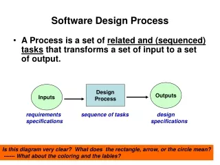
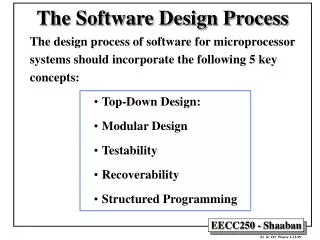
The Software Design Process The design process of software for microprocessor systems should incorporate the following 5 key concepts: • Top-Down Design: • Modular Design • Testability • Recoverability • Structured Programming
Task t Subtask t2 Subtask t1 Subtask t2,2 Subtask t1,2 Subtask t1,1 Subtask t2,1 Subtask t1,1,2 Subtask t1,1,1 Subtask t2,2,2 Subtask t2,2,3 Subtask t2,2,1 Top-down Design • Programming by step-wise refinement; i.e., decompose a large complex project or task into smaller, more manageable components or subtasks. • Iterative process that separates the goals of the program from the methods of achieving them. • Usually accompanied by bottom-up coding. Main task (large) Smaller tasks
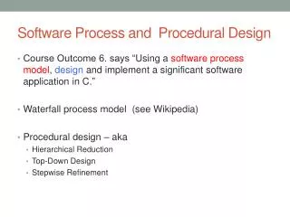
System Specification • Before a system (software or hardware) can be designed, it must be specified. • A system specification provides the statement of the goals that a system should achieve. • The programmer should always validate the end product against these goals. • A tightly-specified system covering many possible cases is usually more reliable than a loosely specified system. • It may also be useful to specify "non-goals"; i.e., things that the system is not required to do.
Single Entry Point Module Module Code (i.e. program) Local Data Storage (cannot be accessed outsides the module) Modular Design • A software module is concerned with a single, logically coherent task. • Modules can be "plugged into the system” and can be supplied by different software vendors . • The internal operation of the module is not significant; only its inputs and outputs. • Modules can be tested separately from the main system. • Coupling indicates how information is shared among modules. Strongly coupled modules share common data which is generally undesirable. • The strength of a module is related to whether or not it performs a single function. Strong modules are easier to test and replace. Single Exit Point
Testability • Testing is done by examining the state of a system at various key points in its lifetime. This can be implemented through the use of breakpoints. • Bottom-up testing: • Involves testing the lowest-level components of a system first. • Starts at the lowest level and keeps moving to higher levels. • Complete when the highest level of the system has been tested. • Requires writing a test driver for the component to be tested. • Top-down testing: • Involves testing the highest levels first. • Helps to spot major design problems early. • Does not require a test driver for components; but instead requires stubs to represent the lower level modules. • White Box versus Black Box testing: • Black Box testing means that the inner workings are totally unknown; thus, all possible inputs and outputs must be tested. • White Box testing means that the inner workings are known; this knowledge can be used to limit the amount of testing required.
Recoverability • Recoverability or exception handling is the ability of a system to cope with erroneous data and to recover from certain classes of errors. • A poor recovery mechanism may be worse than none at all.
Structured Programming • Purpose of structure programming: • Improve programmer productivity; • Make programs easier to read; • Yield more reliable programs. • All programs can be constructed from three fundamental components: • Sequence: • A linear list of actions that are executed in order. • Looping Mechanism: • Permits a sequence to be carried out a number of times. • Decision Mechanism: • Allows one of two courses of action to be taken.
The Conditional Structure For the purpose of the following, assume that 'L' is a logical condition whose result 'B' is stored in register D0 and S, S1 and S2 are sequences. * * IF L THEN S TST.B D0 Test the lower-order byte of D0 BEQ ENDIF If not true, then skip the sequence S ENDIF ... * IF L THEN S1 ELSE S2 * TST.B D0 Test the lower-order byte of D0 BEQ ELSE If not ture, then proceed to the else sequence S1 Execute the S1 sequence BRA ENDIF Skip the else statement ELSE S2 Execute the S2 sequence ENDIF ...
The CASE Statement * CASE I OF * I1: S1 * I2: S2 * ... * In: Sn * MOVE I,D0 Move the variable to D0 for testing CMP I1,D0 Check if it is I1 BEQ ACT1 CMP I2,D0 Check if it is I2 BEQ ACT2 .. CMP In,D0 Check if it is In BEQ ACTn BEQ ERROR ... ACT1 S1 Execute the statement for I1 BRA ENDCASE ACT2 S2 Execute the statement for I2 BRA ENDCASE ... ACTn Sn Execute the statement for In BRA ENDCASE ERROR Handle a value out of range ENDCASE
The CASE Statement • If the conditions can be converted to a sequence of integer numbers, then the CASE statement is more efficiently handled by a jump table: CLR.L D0 Clear all bits of D0 LEA JUMPTAB,A0 Store the address of the jump table MOVE I,D0 Move the variable to D0 for testing CMP I1,D0 Check the bottom of the range BLO ERROR Error if less the lowest value CMP In,D0 Check the top of the range BCS ERROR Error if higher than highest value SUB I1,D0 Get the offset from the first condition ASL.L #2,D0 Multiply by 4, addresses are long words MOVEA.L (A0,D0),A0 Get the address of the action JMP (A0) Jump to the appropriate action ... JUMPTAB DC.L ACT1 First action DC.L ACT2 Second action ... DC.L ACTn N'th action ... ACT1 S1 Execute the statement for I1 BRA ENDCASE ACT2 S2 Execute the statement for I2 BRA ENDCASE ... ACTn Sn Execute the statement for In BRA ENDCASE ERROR Handle a value out of range ENDCASE
Looping Mechanisms * FOR I = N1 TO N2 DO S * MOVE.B #N1,D0 D0 is the loop counter NEXT CMP.B #N2,D0 Check if the end of the loop BHI ENDLOOP Quit the loop if counter too high S Execute the sequence ADDQ #1,D0 Increment the loop counter BRA NEXT ENDLOOP * * FOR I = N DOWNTO 0 * MOVE.W #N,D0 D0 is the loop counter BMI ENDLOOP Skip loop if less than 0 NEXT S Execute the sequence DBRA D0,NEXT Decrement D0 and loop back
DBF Dn,<label> decrement Dn and branch if Dn has not reached -1 Some assemblers allow DBRA instead of DBF
Looping Mechanisms * * WHILE L DO S * REPEAT TST.B D0 Test if the condition still true BEQ ENDLOOP If false, then quit S Execute the sequence BRA REPEAT Repeat the loop ENDLOOP * * REPEAT S UNTIL L * NEXT S Execute the sequence TST.B D0 Test the value of the condition BNE NEXT If not true, then loop again ENDLOOP
Pseudocode, or Program Design Language (PDL) PDL is simply a methodology for expressing the steps of a program before it is translated into assembler. It has the following characteristics: • A compromise between a high-level language description and assembly language. • Facilitates the production of reliable code by providing an intermediate step. • Shares some of the features of high-level languages but without their complexity. • Provides a shorthand notation for the precise description of algorithms. • Can be extended to deal with specific tasks.
Example: Comparing two strings Problem Statement: A sequence of ASCII characters is stored at memory location $600 onward (each character one byte). A second string of equal length is stored at memory location $700 onward. Each string ends with the character $0D (i.e. carriage return). Write a program to determine if these two strings are equal. If they are identical, then place an $FF in D0; otherwise, place the value $00 in D0. First Level PDL - Indicates what to do: Match := false REPEAT Read a pair of characters IF they do not match then EXIT UNTIL a character = $0D Match := true EXIT
Example (continued) Second Level PDL - Elaborates on how to do it: Match := false Set pointer1 to point to String1 Set pointer2 to point to String2 REPEAT Read the character pointed at by String1 Compare with the character pointed at by String2 IF they do not match, THEN EXIT Pointer1 := Pointer1 + 1 Pointer2 := Pointer2 + 1 UNTIL Character = $0D Match := true EXIT
Example: First Assembly Program * D0 Error Flag * A0 Pointer to string 1 * A1 Pointer to string 2 ORG $400 Start of program MOVE.B #$00,D0 Set the flag to fail MOVEA.L #$600,A0 A0 points to string1 MOVEA.L #$700,A1 A1 points to string 2 REPEAT MOVE.B (A0),D1 Get a character from string1 CMP.B (A1),D1 Compare with string2 character BNE EXIT If characters are different exit ADDA.L #1,A0 If the two characters are the ADDA.L #1,A1 same point to the next pair CMP .B #$0D,D1 Test for end of strings BNE REPEAT If not compare next pair MOVE.B #$FF,D0 ELSE Set flag to success EXIT STOP ORG $600 Pointer1 DS.B <length of string1> ORG $700 Pointer1 DS.B <length of string2>
Example: Refined Assembly Code Car_Ret EQU $0D ORG $400 Start of program CLR.B D0 Set the flag to fail LEA Pointer1,A0 A0 points to string1 LEA Pointer2,A1 A0 points to string2 REPEAT MOVE.B (A0),D1 Get character from string1 CMP.B (A1),D1 Compare it with string2 BNE EXIT If different then EXIT LEA 1(A0),A0 Point to next pair of characters LEA 1(A1),A1 CMP.B #Car_Ret,D1 Test for end of strings BNE REPEAT If not then compare next pair MOVE.B #$FF,D0 ELSE set D0 to success EXIT STOP ORG $600 Pointer1 DS.B <length of string1> ORG $700 Pointer1 DS.B <length of string2>