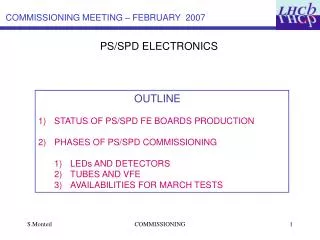
PS/SPD ELECTRONICS
This document outlines the status of the PS/SPD front-end boards' production and testing during the February 2007 commissioning meeting. It highlights key developments, including the completion of pre-production testing of boards, identified issues with specific boards, and the timeline for further production and qualification. The plan includes three phases of commissioning focusing on LEDs, detectors, and VFE components in preparation for March tests. The document emphasizes the importance of thorough evaluation and readiness for upcoming production phases.

PS/SPD ELECTRONICS
E N D
Presentation Transcript
COMMISSIONING MEETING – FEBRUARY 2007 PS/SPD ELECTRONICS • OUTLINE • STATUS OF PS/SPD FE BOARDS PRODUCTION • PHASES OF PS/SPD COMMISSIONING • LEDs AND DETECTORS • TUBES AND VFE • AVAILABILITIES FOR MARCH TESTS COMMISSIONING
1) STATUS OF PS/SPD FE BOARDS PRODUCTION AND TESTS • Pre-production of 14 boards launched after extensive tests of 2 example boards (mostly scrutiny of the trigger part) -> December 2006 • Seven boards received so far (07/02/2006). They were measured OK by the manufacturer. The measurements of the 7 boards lasted one day. • Conclusions / bottomline : • 4 boards are perfectly OK. • 1 board ( 007 ) shows two dead ADC channel (no clock distribution/cured). • 2 boards are off ( 006 & 009 ): TRIG device cannot be (re-)programmed with JTAG (unreachable or programmation failed at the end). Under investigation. • In addition, one component of delay chips on one of these 2 boards ( 006 ) has to be replaced. COMMISSIONING
1) STATUS OF PS/SPD FE BOARDS PRODUCTION AND TESTS • Measurements : • I2C communication • Connectivity • Phasers • Data Processing • Trigger algorithms • DAQ path Most of the answers are binary (error rate compared to a threshold). COMMISSIONING
1) STATUS OF PS/SPD FE BOARDS PRODUCTION AND TESTS Measurements : Quick status Popup link to detailed log Expanded status COMMISSIONING
1) STATUS OF PS/SPD FE BOARDS PRODUCTION AND TESTS Synthesis of the measurements. COMMISSIONING
1) STATUS OF PS/SPD FE BOARDS PRODUCTION AND TESTS Synthesis of the measurements. COMMISSIONING
1) STATUS OF PS/SPD FE BOARDS PRODUCTION AND TESTS • Schedule for the reception of the boards and their qualification: • Preserie : 7 boards received and tested (07/02/07) 7 boards expected for the end of the week Check them extensively and give the green light for production of the serie end of february. • Serie : Start of production expected beginning of April. 6 weeks duration. • Delivery each week of a batch of 16 boards. • Qualification of a board is estimated to be half a day. COMMISSIONING
2) COMMISSIONING OF PS/SPD AND MARCH TEST • There shall be three phases : • 1) LED+DETECTOR (photographs fibre ends at the PMT) • 2) SPD and PS VFE +Tubes (Dedicated systems operated simultaneously to installation). Could start the second week of march. • 3) March test: • Will only have PS cabled. COMMISSIONING
2) COMMISSIONING OF PS/SPD AND MARCH TEST 1) DETECTOR: We do already have a measurement w/ cosmics of all the modules giving the mip photostatistics. We would like to have a measurement of the channels response to LED excitation in the pit. Evgueni demonstrated photographs can be taken at the end of the 64-channels bundle. Allows to check all LEDs / channels / fibres after transportation and installation in the pit. SPD schedule : possible now. PS schedule : seems only possible simultaneously with the VFE electronics installation. See Evgueni’s talk COMMISSIONING
2) COMMISSIONING OF PS/SPD • 2) TUBES AND VFE : SPD • Barcelona team set up a moveable standalone bench to check VFE and tubes (see Xavier’s talk) . • Able to trig autonomously the LED drivers. • Able to supply the HV for the tubes. • Able to supply the LV VFE • Fully checked at lab. Install VFE and check it beginning of march. COMMISSIONING
2) COMMISSIONING OF PS/SPD • 2) TUBES AND VFE : PS • A dedicated system has been set up for testing the PS VFE cabling (See Pascal’s talk). As a by-product, commission tubes, VFE (and FE chain). • The setup is currently tested at home and consists in DC flashing for a short period with a LED matrix the 64-channels in a known order. • Required services : • HV from CW • LV patch panel for VFE boards. • Cooling system not necessary since duration of the test is short. COMMISSIONING
2) COMMISSIONING OF PS/SPD 2) TUBES AND VFE : PS The readout is performed with one PS/SPD FE Board. Output : store channel response in an electronics logbook. Schedule : simultaneous to VFE installation and cabling. Start of the operation for the beginning of March. COMMISSIONING
2) COMMISSIONING OF PS/SPD 3) MARCH TESTS: Availability of the electronics : SPD VFE : installed and checked but not cabled PS VFE : in principle OK w/ the installation schedule. PS/SPD FE Boards : the target is to fill a crate. Consistent with the production planning. SPD Control Board : 4 protoypes already available. COMMISSIONING
2) COMMISSIONING OF PS/SPD 3) MARCH TESTS: AIM I At first, use PS/SPD FE Rams to inject signals. Common test last november was very useful. Software ECAL/PS is ready for that purpose. Generate random patterns and check the response. The minor issues reported from the common test on the PS/SPD TRIG device are solved (neighbours phase, BCIDreset convention(s) …). COMMISSIONING
2) COMMISSIONING OF PS/SPD • 3) MARCH TESTS: • Automated processes under CAT exist to deal with : • Tests of connectivity • Setting the phasers ECAL and PS/SPD neighbours inputs. • Check internally algorithms • Define the pipelines for ECAL and PSFE neighbours inputs • Common software to check the correctness of the whole response at the TVB level. • AIM I Reproduce the common test and extend it to a crate. COMMISSIONING
2) CONCLUSION 3) MARCH TESTS: AIM II Use PS LEDs. Simultaneous light on 64-channels of a tube. One important goal would be to set up procedures to align in time the boards by tuning the start of the VFE charge integration, dealing with the different lengthes of fibre bundles. INTENTIONS (open questions) Define how to dispose the (hopefully) available 14 FE boards. Reads one supermodule ? Reads a crate ? Check full board / half board configurations …. COMMISSIONING