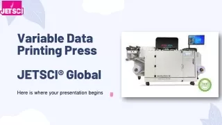
Automated Printing Press Design with Ultrasonic Sensors for Enhanced Efficiency
This project explores an automated printing press system designed to optimize mechanical procedures, significantly reducing labor costs and time. Key features include programmable control via a user-friendly interface, ultrasonic sensors for object detection, and a mechanical setup with velocity and position controlled motors. The system offers a more cost-effective controller with benefits such as improved printing quality and error tolerance. Ethical concerns regarding hardware malfunctions are also addressed, ensuring operator safety.

Automated Printing Press Design with Ultrasonic Sensors for Enhanced Efficiency
E N D
Presentation Transcript
ECE 445: Printing Press Jerome Han John Doherty Adriana Siu TA: Kieran Levin Profesor: Scott Carney
Introduction and Objectives Overview Benefits and Features • Mechanical Setup • The film system • The print system • External control panel • Ultrasonic sensors • Automation of all mechanical procedure (saves labor cost and time) • More cost effective controller • Easy user interface • Programmable
Content: Mechanical Build • Unwind Roller • *1st set for tension/distance(2 rollers) • Printing (3 rollers) • Rewind Roller • 4 sensor mounts • 2 bottom • *2 sides
Content: “Velocity Controlled Motor” • Analog Voltage Reference α Speed • Pn300=12V/rated speed (12V=3000RPM, 6V=1500RPM) • Microcontroller outputs PWM at f=490Hz • PWM=>RC LP Filter=>Analog Voltage • *Relation: Duty Cycle of PWM vs. RPM:
Content: “Position Controlled Motor” • Pulse Train Reference α • Speed of motor (frequency of pulses) & • distance traveled by motor shaft (number of pulses) • Time b/w pulse trains α • Delay b/w distance traveled • Reference units:
Content: Front Panel • On-Off switch -Turn on and off the motors and disables the control panel • Potentiometer -Controls the speed of the velocity motor with in a jog mode • Matrix Keypad -Changes the presets of the motors • LEDs -Indicates the status of the motors • Further Tests • Switch
Content: Ultrasonic Sensors Theory • Sends ultrasonic waves to object and receives reflected waves for detection • Use 1 digital pin for trigger output/echo input • Operating Frequency of 40 kHz • Theoretical Minimum and Maximum range from 3cm to 4m
Content: Ultrasonic Sensors: Discussion and Tolerance • Sources of Error • Data acquisition from oscilloscope • Measurement of width from oscilloscope • Inconsistency in object detection • Placement in mechanical setup • Improvement • Tolerance Analysis
Recommendations and Conclusion: Design Improvement • Motors • Balance velocity voltage output (*D/A converter, tension control) • Mechanical: More distance for no crinkle in paper • Front Panel • LCD screen • Sensors • Mechanical: Side placements too low • Printing Press worked! • Different speeds and distance b/w prints
Ethical Concerns • Hardware malfunctions • Could hurt somebody (ink in their eyes) • Getting their hand caught in the rollers if the ultrasonic sensors malfunction and don’t detect hand • SRf05 low cost so they can get damaged easily • Control panel buttons are very small and this might confuse the operator (no red for stop or green for go buttons)