Download
1 / 96
960 likes | 1.35k Vues
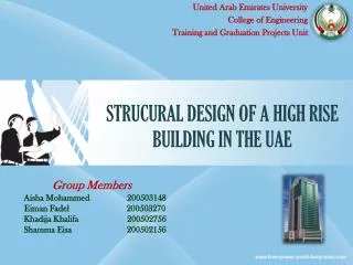
United Arab Emirates University College of Engineering Training and Graduation Projects Unit. STRUCURAL DESIGN OF A HIGH RISE BUILDING IN THE UAE. Group Members : Aisha Mohammed 200503148 Eiman Fadel 200503270

E N D
United Arab Emirates University College of Engineering Training and Graduation Projects Unit STRUCURAL DESIGN OF A HIGH RISE BUILDING IN THE UAE Group Members : Aisha Mohammed 200503148 EimanFadel 200503270 KhadijaKhalifa 200502756 ShammaEisa 200502156
Table Of Content • Introduction • GPI • SAFE Model • Punching Shear • Beam Design • Structural Drawings • ETAB Model • Shear Wall Design • Plies layout • Cost Estimation • Environmental Impact • Conclusion
Introduction • High rise buildings are generally built to take advantage of their height since the significant margin between their width and height. • Looking at the country construction boom at this time we realized the importance of being able to structurally design this type of buildings before graduating. • Therefore we choose to design a high rise building in the UAE using the required codes, software, considering all the possible solutions and taking in account the effect of the project in the environment
GPI Summary • The project vision is to develop a structural design of a high rise building (tower) in the United Arab Emirates especially in Dubai city • The tower consists of 4 basements, 4 podiums and 24 stories. • In this project a tower was selected from several alternatives. • Applicable international codes of practice were reviewed • Based on the literature review, the structural system of the tower was developed .
GPI Summary • Preliminary structural design of the typical floor slab was conducted. • Preliminary cost estimation was preformed. • The effect of the project on the environment was considered, Ethics and contemporary issues were highlighted • Finally, the project management was studied and presented.
SAFE Model • It is a program used to analyze and design structural elements. • We used SAFE software to design the slab of the typical floor in GPI. • We used it manly for the gravity load calculation. • By obtaining the moment for the program we designed the steel detailing for the slab.
Typical story SAFE Model (NEW) Transfer the columns into Shear walls in both sides Extend the Shear walls all the way & making them equal at the top
Basement SAFE Model Supporting columns Extended Shear walls
Podium SAFE Model 3D Masonry Wall Same as Basement
Podiums SAFE Model 2D Masonry Wall
System change in 23rd Floor Huge Size Reduction Totally Different layout
23rd Floor SAFE model Extended Edges
23rd Floor SAFE model In 23rd floor we add some beams; because of the architectural reasons we cant add more shear walls between the slabs ( long spans). This beams are more safe to support the floor
23rd Floor SAFE model More Obvious display for the beams
System change in the 24th Floor Floor Boundary Double height Beams Added carry the load
24th Floor SAFE model Extended Edges In the 24 story we add two large voids because the room is used for special purpose events.
24th Floor SAFE model Same beams which showed up in the 23th floor with small difference
System change in the Roof Floor Boundary
Roof SAFE model Roof Story is the Same as 24th Story , No Voids Now. Extended Edges
SAFE Model Analysis • To analyze our structural system we run the SAFE file to get the moment in x-direction and y-direction for the whole building slabs. • after that we took a mesh in the both direction top and bottom and it was considered as 5 bars No.13 /m. • Then we entered the moment which can resist the mesh in the safe model the extra steel needed. • Next we took the moment in the places which needs extra steel, and we put it in the excel sheet to get the number of bars needed in that location • Finally, subtracting the mesh steel area we get the amount of extra steel needed
ShearWallPunchingShear • Shear wall dimension = 400 x 1400 mm • Depth = (thickness slab) – cover =(260)- 25 = 235 mm • Yc = 23.6 KN/m2 • Fc’= 28 Mpa • WD= (ts x yc )+ SDD = 0.260 x 23.6 + 6.1 = 12.236 KN/m2 • WL = 5 KN/m2 • Wsu= 1.2 WD + 1.6 WL = 1.2 (12.236 ) + 1.6 (5) = 22.6832 KN/m2 • Tributary area : L1= 6530 mm , L2= 9147 mm
ShearWallPunchingShear • Get the Ultimate Shear Force = 22.6832 [(6.53*9.147) - (0.4+ 0. 235)(4.1 + 0. 235) ] = 1292.4 KN = 2 (0.4) + 2 (4.1) + 4(0. 235) = 9.94 m = 9940 mm • Smallest values form three equations to get Vc,p: • =1/ 3 * 280.5 * 9940 * 235/1000 = 2335.9 KN • = (2 + ( 4 / 10.25 )) x ( (280.5 * 9940 * 235) /( 12 * 1000)) = 2462.04 KN
ShearWallPunchingShear • = (2 + (30*235)/ 9940) x ( (280.5 * 9940 * 235) /( 12 * 1000) ) = 2790.6 KN • Hence, the smallest vale VC.P= 2335.9 KN • Where Ф = 0.75 1292.4 ≤ 1751.925 OK Safe
Column PunchingShear • We used column head for the columns to increase the area so the load will distribute • Columns dimension = 2000 x 2000 mm • Depth = (thickness slab + thickness of drop panel) – cover = (260+140) – 25 = 375 mm • Yc = 23.6 KN/m2 • Fc’= 28 Mpa • WD= (ts x yc) + SDD = 0. 375x 23.6 + 6.1 = 14.95 KN/m2 • WL = 5 KN/m2 • Wu= 1.2 WD + 1.6 WL = 1.2 (14.95 ) + 1.6 (5) = 25.94 KN/m2 • Tributary area : L1=9009 mm , L2= 6772 mm
Column PunchingShear • Vu = 1459.4 KN • VC.P= 5002.1 KN • Where Ф = 0.75 1459.4 ≤ 3751.6 OK Safe • Note that; the drop panel side dimension is typically taken as (average span / 3) Average span = (left span +right span)/2
Basement Structural Drawings X-direction Drop Panels With extra RC
Beams Design • For the last three floors which, the structural system had been changed because of the slab area decreased so much that many shear columns had been canceled. • Also due to architectural purposes the 24th floor have a double height so for all that reasons we add beams • We draw the beams in the SAFE model and we tooke the moment after we run it. • Then we entered the moment on excel which we developed to get the number of steel bars needed to resist the moment.