Download
1 / 19
190 likes | 369 Vues
Beam Test Results and ORCA validation for CMS EMU CSC front-end electronics. N. Terentiev Carnegie Mellon University CMS EMU Meeting, Fermilab October 21, 2005. Outline. Beam Test Data vs. ORCA Simulation (cathode strip signal shape and cross-talk).

E N D
Beam Test Results and ORCA validation for CMS EMU CSC front-end electronics N. Terentiev Carnegie Mellon University CMS EMU Meeting, Fermilab October 21, 2005
Outline • Beam Test Data vs. ORCA Simulation (cathode strip signal shape and cross-talk). • EMU CSC Slice Test Data Grid Transfer (CERN to FNAL). • Plans.
Beam Test Data vs ORCA Simulation • Motivation: • Validation of ORCA simulation is a part of Physics TDR, Vol. 1. • Importance of realistic simulation of CSC input signals and electronics response (the coordinate and time resolution, L1 trigger primitives, pile-up, neutron background). • Old (prototype) front-end electronics parameters are still in use in ORCA simulation. • New parameters matching final cathode amplifier design and pulser strip cross-talk data are now available (S. Durkin, OSU).
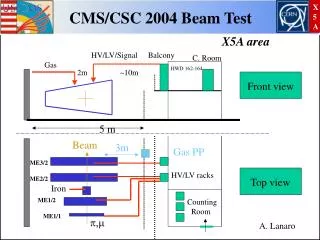
Beam Test Data vs ORCA Simulation • Conditions: • Beam test data - CERN H2 Muons 150 GeV, 25 ns structured beam, Oct. 2004, Track Finder Trigger. • Simulation - ORCA_8_7_1, OSCAR_3_7_0. (in CMS detector geometry), single muon track with Pt = 100 Gev, generated flat in Eta and Phi, cut 1.3 < EtaGen < 1.6 ( ~ as in the beam test ), hits from CSC ME234/2 only. • Select one anode hit and one cathode comparator hit per CSC layer in beam test data.
Fitting function for signal from one cathode strip: signal is sampled in a Switch Capacitor Array (SCA) in 8 time bins each 50 ns long; “semi-Gaussian” fit S(t)~Q*T**4* exp(-T), Q = charge, ADC counts, T = (t-Ts)/T0, 4*T0 = peaking time, ns Ts = arrival time, ns; note example with two pulse positions 25 ns apart and having max. SCA at one and the same SCA time bin. Additional Ts smearing due to CSC drift time. Beam Test Data vs ORCA Simulation
Beam Test Data vs ORCA Simulation • Including strip to strip cross-talk: • Based on external pulser strip data taken at SX5 (S. Durkin, J. Gilmore, F. Geurts, April 2005). • Cross-talk is modeled by cross-talk from pulser data, convoluted with ion drift time 1/(t+2.1) and a 50 ns square wave drift electron arrival (S. Durkin). • The function buckeye_pulse_full(t,P0,P1,Z1) (S. Durkin) approximates the shape of the cross-talk to ~1% near the peak. • Cross-talk from the strip with charge Q to the side strip: cross-talk(t) = Q * Ct * Fc(t), Fc(t) = buckeye_pulse_full(t,P0,P1,Z1)/N, N = fixed normalization factor, depending on P0,P1,Z1, Ct = cross-talk coefficient. • Separate fit of the cross-talk pulser data with free P0,P1,Z1 and Ct (Q =1) yields Ct ~ 0.1 . • Use Fc(t) with fixed P0, P1, Z1 and free Ct to fit cross-talk in the beam test data (and in ORCA data as well though ORCA simulation used different function…)
Beam Test Data vs ORCA Simulation • Fitting function for 12 SCA time bins in 3 strips: SCA_left(t) = Q_left * S(t) + Ct*Fc(t)*(0 + Q_middle ) SCA_middle(t)= Q_middle* S(t) + Ct*Fc(t)*(Q_left + Q_right ) SCA_right(t) = Q_right * S(t) + Ct*Fc(t)*(Q_middle+ 0 ) where S(t,T0,Ts)– semi-Gaussian signal, Fc(t)– cross-talk shape. Six fitted parameters: charges Q_left, Q_middle, Q_right; peaking and arrival timeT0, Ts andcross-talk Ctat NDF = 6. • Table: Example of ADC counts in SCA time bins in 3 cathode strips.
Beam Test Data vs ORCA Simulation • Results • The peaking time T0 is one and the same in all three types of data. • The cross-talk Ct in ORCA simulation is lower than in beam test and pulser data likely due to simplified cross-talk description in ORCA.
Beam Test Data vs ORCA Simulation Beam Test Data ORCA Simulation
Beam Test Data vs ORCA Simulation Beam Test Data ORCA Simulation
Beam Test Data vs ORCA Simulation Beam Test Data:Cathode strip SCA arrival time Ts for one CSC layer and averaged over >= 4 CSC layers. The peaks are 25 ns apart.
Restoring cathode strip pulse shape with use of fitted arrival time Ts: Since Ts is scattered SCA samples the pulse in different points in each event. Eliminate the Ts dependence of SCA(t) by subtracting Ts from t of all eight SCA samples in each event. The result is the restored pulse shape measured in much more time points than original 8 time bins. Averaging SCA(t - Ts)/Q for each 6.25 ns time bin gives the detailed pulse shape (see next slide). Beam Test Data vs ORCA Simulation
Beam Test Data vs ORCA Simulation Beam Test Data ORCA, Pulser and Beam Test Data
Single electron response function: ORCA makes use of old cathode amplifier single electron response function. The new function is available (S. Durkin). Difference is small. For consistency, the new single electron response function should replace the old one in ORCA simulation. Beam Test Data vs ORCA Simulation
Measuring cross-talk in data with subtracted Ts: Cross-talk as the ratio of one side strip SCA to the central strip SCA plus both side strips SCA for given time bin. In the pulser data only central strip was pulsed – subtract the fitted values Q_left*S(t) and Q_right*S(t) in beam test and ORCA data. Reasonable agreement between the beam test and pulser data cross-talks. The cross-talk in ORCA simulation is different from one in the beam test and pulser data. Beam Test Data vs ORCA Simulation
Beam Test Data vs. ORCA Simulation (conclusion) • Cathode strip signal shape. • The shapes of the cathode strip output pulse in ORCA simulation and data are very similar. For consistency, the new single electron response function should replace the old one in ORCA simulation. • Cathode strip cross-talk. • The beam test and pulser data cross-talks are similar. The cross-talk in ORCA simulation should be updated with use of functions obtained by S. Durkin. • Developed methods: • Averaged fitted arrival time Ts can help with timing. This cathode beam crossing time was compared with ALCT anode BX time by S. Durkin and a good agreement was found. • Allow to calibrate cross-talk for each cathode strip using fitted coefficient Ct, offset and slope of the SCA ratio vs. t-Ts dependence. • Details are in http://www-hep.phys.cmu.edu/cms/TALKS/ORCA_vs_BT04/text_v2a.html and will go to the CMS internal note for Physics TDR, Vol. 1. • Thanks to S. Durkin for very helpful discussions and pulser data.
EMU CSC Slice Test Data Transfer CERN-FNAL. • Temporary solution (prior to use of Global DAQ and official Data Transfer Tools): • Grid tools (vdt package and srm client) were installed on emuslice02 machine of EMU Slice Test (SX5,CERN). Thanks to I. Vorobiev (CMU), Yujun Wu (FNAL) for help. • One simple script controls the automated data transfer from emuslice02 local disk to dCache resilient area at Fermilab: - checks the presence of completed and copied to CERN Castor data files on disk; - checks the list of available files against the list of copied to Fermilab files; - runs cksum and stores result for the file to be copied; - transfers file to Fermilab dCache resilient area by srmcp; - adds the file name to the list of copied files; - makes corresponding record in the log; - sleeps for N second.
EMU CSC Slice Test Data Transfer CERN-FNAL (cont’d) • Temporary solution (prior to use of Global DAQ and official Data Transfer Tools): • Typical data file is 0.3 - 0.5 GB (50,000 ev), transfer rate 1.5 - 2 min. • dCache resilient area has several copies on different disks, provides immediate access to the files (from/to UAF cluster or the grid client), but does not have tape backup (our responsibility). • This temporary solution can be useful in future (copies of files from EMU local DAQ machines?).
Plans • The beam test data vs. ORCA simulation comparison – done for cathode strip signal shape and cross-talk. Corrections will be done during ORCA to CMSSW transition. • Minor updates/modifications of the SX5-dCache data transfer script to allow to monitor transfer here, at LPC control room at Fermilab. • Main focus now on porting ORCA EMU CSC code to new framework, EDM/CMSSW. The work has been started in LPC Muon group to port raw data unpacking and digis and begin to use CMSSW in Slice Test data analysis (see the talk by M. Schmitt).