Download
1 / 92
930 likes | 969 Vues
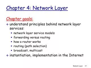
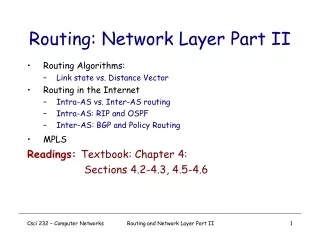
Routing: Network Layer Part II. Routing Algorithms: Link state vs. Distance Vector Routing in the Internet Intra-AS vs. Inter-AS routing Intra-AS: RIP and OSPF Inter-AS: BGP and Policy Routing MPLS Readings: Textbook: Chapter 4: Sections 4.2-4.3, 4.5-4.6. 5. 3. 5.

E N D
Routing: Network Layer Part II • Routing Algorithms: • Link state vs. Distance Vector • Routing in the Internet • Intra-AS vs. Inter-AS routing • Intra-AS: RIP and OSPF • Inter-AS: BGP and Policy Routing • MPLS Readings: Textbook: Chapter 4: Sections 4.2-4.3, 4.5-4.6 Routing and Network Layer Part II
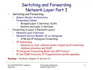
5 3 5 2 2 1 3 1 2 1 F D E B C A Routing & Forwarding:Logical View of a Router Routing and Network Layer Part II
IP Forwarding Process 1. Remove a packet from an input queue 2. Check for sanity, decrement TTL field 4. Place packet on correct output queue Forwarding Process 3. Match packet’s destination to a table entry If queues get full, just drop packets! If queues get full, just drop packets! IP Forwarding Table Router
IP Forwarding Table Destination Next Hop Interface Net A Router 1 INT 7 Net B Direct INT 4 Net C, Host 3 Router 2 INT 3 Net C Router 1 INT 7 A destination is usually a network. May also be a host, or a “gateway of last resort” (default) The next hop is either a directly connected network or a router on a directly connected network A physical interface
How Are Forwarding Tables Populated to Implement Routing? Dynamically Statically Routers exchange network reachability information using ROUTING PROTOCOLS. Routers use this to compute best routes Administrator manually configures forwarding table entries + Can rapidly adapt to changes in network topology + Can be made to scale well - Complex distributed algorithms - Consume CPU, Bandwidth, Memory - Debugging can be difficult - Current protocols are destination-based + More control + Not restricted to destination-based forwarding - Doesn’t scale - Slow to adapt to network failures In practice : a mix of these. Static routing mostly at the “edge”
Dynamic Routing: Intra- vs. Inter-AS OSPF BGP AS 1 IGP = Interior Gateway Protocol EIGRP Metric based: OSPF, IS-IS, RIP, EIGRP (cisco) AS 2 EGP = Exterior Gateway Protocol Policy based: BGP The Routing Domain of BGP is the entire Internet Routing and Network Layer Part II
Internet AS Hierarchy border (exterior gateway) routers interior routers Routing and Network Layer Part II
Inter-AS routing between A and B b c a a C b B b c a d Host h1 A A.a A.c C.b B.a Intra-AS vs. Inter-AS Routing Host h2 Intra-AS routing within AS B Intra-AS routing within AS A Routing and Network Layer Part II
“Gateways”: • perform inter-AS routing amongst themselves • perform intra-AS routing with other routers in their AS b a a C B d c A b b a c network layer inter-AS, intra-AS routing in gateway A.c link layer A.a C.b B.a A.c Intra-AS and Inter-AS Routing physical layer Routing and Network Layer Part II
OSPF Process OSPF Routing tables RIP Process RIP Routing tables BGP Process BGP Routing tables Where Does Forwarding Table Come From? BGP RIP Domain OSPF Domain Forwarding Table Manager Forwarding Table
5 3 5 2 2 1 3 1 2 1 C D E B A F Routing • Goal: determine a “good” path through the network from source to destination • Good means usually the shortest path • Network modeled as a graph • Routers nodes • Link edges • Edge cost: delay, congestion level,… Routing and Network Layer Part II
5 3 5 2 2 1 3 1 2 1 C D E B A F Basic Routing Problem • Assume • A network with N nodes, where each edge is associated a cost • A node knows only its neighbors and the cost to reach them • How does each node learn how to reach every other node along the shortest path? Routing and Network Layer Part II
Routing: Issues • How are routing tables determined? • Who determines table entries? • What info is used in determining table entries? • When do routing table entries change? • Where is routing info stored? • How to control routing table size? Answer these questions, we are done! Routing and Network Layer Part II
Routing Paradigms • Hop-by-hop Routing • Each packet contains destination address • Each router chooses next-hop to destination • routing decision made at each (intermediate) hop! • packets to same destination may take different paths! • Example: IP’s default datagram routing • Source Routing • Sender selects the path to destination precisely • Routers forward packet to next-hop as specified • Problem: if specified path no longer valid due to link failure! • Example: • IP’s loose/strict source route option • virtual circuit setup phase in ATM (or MPLS) Routing and Network Layer Part II
Routing Algorithms/Protocols Issues Need to Be Addressed: • Route selection may depend on different criteria • Performance: choose route with the smallest delay • Policy: choose a route that doesn’t cross .gov network • Adapt to changes in network topology or condition • Self-healing: little or no human intervention • Scalability • Must be able to support a large number of hosts, routers Routing and Network Layer Part II
Centralized vs. Distributed Routing Algorithms Centralized: • A centralized route server collects routing information and network topology, makes route selection decisions, then distributes them to routers Distributed: • Routers cooperate using a distributed protocol • to create mutually consistent routing tables • Two standard distributed routing algorithms • Link State (LS) routing • Distance Vector (DV) routing Routing and Network Layer Part II
Link State vs Distance Vector • Both assume that • The address of each neighbor is known • The costof reaching each neighbor is known • Both find global information • By exchanging routing info among neighbors • Differ in the information exchanged and route computation • LS: tells every other node its distances to neighbors • DV: tells neighbors its distance to every other node Routing and Network Layer Part II
Link State Algorithm • Basic idea: Distribute link state packet to all routers • Topology of the network • Cost of each link in the network • Each router independently computes optimal paths • From itself to every destination • Routes are guaranteed to be loop free if • Each router sees the same cost for each link • Uses the same algorithm to compute the best path Routing and Network Layer Part II
Host C Host D Host A N2 N1 N3 N5 Host B Host E N4 N6 N7 Link State: Control Traffic • Each node floods its local information to every other node in the network • Each node ends up knowing the entire network topology use Dijkstra to compute the shortest path to every other node Routing and Network Layer Part II
C C C C C C C A A A A A A A D D D D D D D Host C Host D Host A B B B B B B B E E E E E E E N2 N1 N3 N5 Host B Host E N4 N6 N7 Link State: Node State Routing and Network Layer Part II
Topology Dissemination • Each router creates a set of link state packets (LSPs) • Describing its links to neighbors • LSP contains • Router id, neighbor’s id, and cost to its neighbor • Copies of LSPs are distributed to all routers • Using controlled flooding • Each router maintains a topology database • Database containing all LSPs Routing and Network Layer Part II
5 3 5 2 2 1 3 1 2 1 A D B E F C Topology Database: Example link state database Routing and Network Layer Part II
Constructing Routing Table:Dijkstra’s Algorithm • Given the network topology • How to compute the shortest path to each destination? • Some notation • X: source node • N: set of nodes to which shortest paths are known so far • N is initially empty • D(V): the cost of the known shortest path from source X to V • C(U,V): cost of link U to V • C(U,V) = if not neighbors Routing and Network Layer Part II
Algorithm (at Node X) • Initialization • N = {X} • For all nodes V • If Vadjacent to X, D(V) = C(X,V) else D(V) = • Loop • Find U not in N such that D(U) is the smallest • Add U into set N • Update D(V) for all V not in N • D(V) = min{D(V), D(U) + C(U,V)} • Until all nodes in N Routing and Network Layer Part II
C D A E B F Example: Dijkstra’s Algorithm D(B),p(B) 2,A D(D),p(D) 1,A D(C),p(C) 5,A D(E),p(E) Step 0 1 2 3 4 5 start N A D(F),p(F) 1 Initialization: 2 N = {A}; 3 for all nodes v 4 if v adjacent to A 5 then D(v) = c(A,v); 6 else D(v) = ; … 5 3 5 2 2 1 3 1 2 1 Routing and Network Layer Part II
… • 8 Loop • 9 find w not in N s.t. D(w) is a minimum; • 10 add w to N; • update D(v) for all v adjacent • to w and not in N: • 12 D(v) = min( D(v), D(w) + c(w,v) ); • 13 until all nodes in N; D C A E B F Example: Dijkstra’s Algorithm D(B),p(B) 2,A D(D),p(D) 1,A D(C),p(C) 5,A 4,D D(E),p(E) 2,D Step 0 1 2 3 4 5 start N A AD D(F),p(F) 5 3 5 2 2 1 3 1 2 1 Routing and Network Layer Part II
… • 8 Loop • 9 find w not in N s.t. D(w) is a minimum; • 10 add w to N; • update D(v) for all v adjacent • to w and not in N: • 12 D(v) = min( D(v), D(w) + c(w,v) ); • 13 until all nodes in N; D C A E B F Example: Dijkstra’s Algorithm D(B),p(B) 2,A D(D),p(D) 1,A D(C),p(C) 5,A 4,D 3,E D(E),p(E) 2,D Step 0 1 2 3 4 5 start N A AD ADE D(F),p(F) 4,E 5 3 5 2 2 1 3 1 2 1 Routing and Network Layer Part II
… • 8 Loop • 9 find w not in N s.t. D(w) is a minimum; • 10 add w to N; • update D(v) for all v adjacent • to w and not in N: • 12 D(v) = min( D(v), D(w) + c(w,v) ); • 13 until all nodes in N; D C A E B F Example: Dijkstra’s Algorithm D(B),p(B) 2,A D(D),p(D) 1,A D(C),p(C) 5,A 4,D 3,E D(E),p(E) 2,D Step 0 1 2 3 4 5 start N A AD ADE ADEB D(F),p(F) 4,E 5 3 5 2 2 1 3 1 2 1 Routing and Network Layer Part II
… • 8 Loop • 9 find w not in N s.t. D(w) is a minimum; • 10 add w to N; • update D(v) for all v adjacent • to w and not in N: • 12 D(v) = min( D(v), D(w) + c(w,v) ); • 13 until all nodes in N; D C A E B F Example: Dijkstra’s Algorithm D(B),p(B) 2,A D(D),p(D) 1,A D(C),p(C) 5,A 4,D 3,E D(E),p(E) 2,D Step 0 1 2 3 4 5 start N A AD ADE ADEB ADEBC D(F),p(F) 4,E 5 3 5 2 2 1 3 1 2 1 Routing and Network Layer Part II
… • 8 Loop • 9 find w not in N s.t. D(w) is a minimum; • 10 add w to N; • update D(v) for all v adjacent • to w and not in N: • 12 D(v) = min( D(v), D(w) + c(w,v) ); • 13 until all nodes in N; D C A E B F Example: Dijkstra’s Algorithm D(B),p(B) 2,A D(D),p(D) 1,A D(C),p(C) 5,A 4,D 3,E D(E),p(E) 2,D Step 0 1 2 3 4 5 start N A AD ADE ADEB ADEBC ADEBCF D(F),p(F) 4,E 5 3 5 2 2 1 3 1 2 1 Routing and Network Layer Part II
5 3 5 2 2 1 3 1 2 1 A D B E F C Dijkstra’s Algorithm: In a Nutshell D(B),p(B) 2,A 2,A 2,A D(D),p(D) 1,A D(C),p(C) 5,A 4,D 3,E 3,E D(E),p(E) infinity 2,D Step 0 1 2 3 4 5 start N A AD ADE ADEB ADEBC ADEBCF D(F),p(F) infinity infinity 4,E 4,E 4,E Routing and Network Layer Part II
5 3 5 2 2 1 3 1 2 1 A D E B F C Routing Table Computation Routing and Network Layer Part II
Distance Vector Routing • A router tells neighbors its distance to every router • Communication between neighbors only • Based on Bellman-Ford algorithm • Computes “shortest paths” • Each router maintains a distance table • A row for each possible destination • A column for each neighbor • DX(Y,Z) : distance from X to Y via Z • Exchanges distance vector (the table) with neighbors • Distance vector: current least cost to each destination Routing and Network Layer Part II
Host C Host D Host A N2 N1 N3 N5 Host B Host E N4 N6 N7 Distance Vector: Control Traffic • When the routing table of a node changes, the node sends its table to its neighbors • A node updates its table with information received from its neighbors Routing and Network Layer Part II
cost to destination via E 1 A 1 7 8 10 B 14 8 9 11 D 11 5 4 2 D () A B C D 6 2 8 1 2 D A E B C destination Distance Table: Example Routing and Network Layer Part II
cost to destination via Outgoing link to use, cost A B C D A,1 D,5 D,4 D,2 E D () A B C D A 1 7 6 4 B 14 8 9 11 D 5 5 4 2 destination destination Routing table Distance table Distance Table to Routing Table Routing and Network Layer Part II
iterative: continues until no nodes exchange info. self-terminating: no “signal” to stop asynchronous: nodes need not exchange info/iterate in lock step! distributed: each node talks only with directly-attached neighbors Distance Table data structure each node has its own row for each possible destination column for each directly-attached neighbor to node example: in node X, for dest. Y via neighbor Z: distance from X to Y, via Z as next hop X = D (Y,Z) Z c(X,Z) + min {D (Y,w)} = w Distance Vector Routing Algorithm Routing and Network Layer Part II
Iterative, asynchronous: each iteration caused by: local link cost change message from neighbor: its least cost path change from neighbor Distributed: each node notifies neighbors only when its least cost path to any destination changes neighbors then notify their neighbors if necessary Each node: Distance Vector Routing: Overview waitfor (change in local link cost or msg from neighbor) recomputedistance table if least cost path to any dest has changed, notify neighbors Routing and Network Layer Part II
2 1 7 Y Z X X c(X,Y) + min {D (Z,w)} c(X,Z) + min {D (Y,w)} D (Y,Z) D (Z,Y) = = w w = = 2+1 = 3 7+1 = 8 X Z Y Distance Vector Algorithm: Example Routing and Network Layer Part II
2 1 7 X Z Y Distance Vector Algorithm: Example Routing and Network Layer Part II
1 4 1 50 X Z Y Convergence of DV Routing • router detects local link cost change • updates distance table • if cost change in least cost path, notify neighbors algorithm terminates “good news travels fast” Routing and Network Layer Part II
60 4 1 50 X Z Y Problems with DV Routing • Link cost changes: • good news travels fast • bad news travels slow • “count to infinity” problem! algorithm continues on! Routing and Network Layer Part II
X Y Z Count-to-Infinity Problem 1 1 2 Routing and Network Layer Part II
“Fixes” to Count-to-Infinity Problem • Split horizon • A router neveradvertises the cost of a destination to a neighbor • If this neighbor is the next hop to that destination • Split horizon with poisonous reverse • If X routes traffic to Z via Y, then • X tells Y that its distance to Z is infinity • Instead of not telling anything at all • Accelerates convergence Routing and Network Layer Part II
60 4 1 50 X Z Y Split Horizon with Poisoned Reverse • If Z routes through Y to get to X : • Z tells Y its (Z’s) distance to X is infinite (so Y won’t route to X via Z) algorithm terminates Routing and Network Layer Part II
W X Y Z Count-to-Infinity Problem Revisited Routing and Network Layer Part II
Tells everyone about neighbors Controlled flooding to exchange link state Dijkstra’s algorithm Each router computes its own table May have oscillations Open Shortest Path First (OSPF) Tells neighbors about everyone Exchanges distance vectors with neighbors Bellman-Ford algorithm Each router’s table is used by others May have routing loops Routing Information Protocol (RIP) Link State vs Distance Vector Routing and Network Layer Part II
Message complexity LS: O(n2*e) messages n: number of nodes e: number of edges DV: O(d*n*k) messages d: node’s degree k: number of rounds Time complexity LS: O(n*log n) DV: O(n) Convergence time LS: O(1) DV: O(k) Robustness: what happens if router malfunctions? LS: node can advertise incorrect link cost each node computes only its own table DV: node can advertise incorrect path cost each node’s table used by others; error propagate through network Link State vs. Distance Vector (cont’d) Routing and Network Layer Part II
scale: with 200 million destinations: can’t store all dest’s in routing tables! routing table exchange would swamp links! administrative autonomy internet = network of networks each network admin may want to control routing in its own network Routing in the Real World • Our routing study thus far - idealization • all routers identical • network “flat” • How to do routing in the Internet • scalability and policy issues Routing and Network Layer Part II
Routing in the Internet • The Global Internet consists of Autonomous Systems (AS) interconnected with each other hierarchically: • Stub AS: small corporation: one connection to other AS’s • Multihomed AS: large corporation (no transit): multiple connections to other AS’s • Transit AS: provider, hooking many AS’s together • Two-level routing: • Intra-AS: administrator responsible for choice of routing algorithm within network • Inter-AS: unique standard for inter-AS routing: BGP Routing and Network Layer Part II