Download

1 / 21
210 likes | 239 Vues
Explore various types of fittings, thread sizes, tube materials, and industry-specific fittings for pneumatic systems. Learn about standards, sealing techniques, and essential information for interconnecting components.

E N D
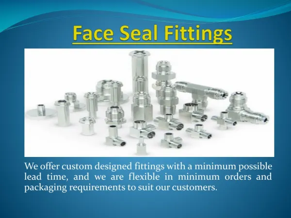
Fittings and Tube For the interconnection of pneumatic components and systems
Contents Introduction Presentations • Thread sizes • Pneufit • Push-on fittings • Tube sizes and materials • External nut compression • Fitting types • Internal nut compression • Industry specific fittings • BSP and Hose fittings • General purpose fittings • FleetFit (vehicle fittings) • Function fittings • WeldFit (welding industry ) • Standards • Plasfit (brewing industry) • Sealing the thread • Taper and parallel • Tube and Hose • Pressures / temperatures • Click the section or presentation to go to it
Introduction • Fittings connect the components of a pneumatic system with flexible tubing, hose and rigid pipe • A variety of fittings ranges are produced to fulfil the needs of general and specific industries • The variables include: • methods of connection • thread sizes • tube sizes • angles of connection • number of connections • materials of construction • applications • industry standards
Thread sizes • For the majority of pneumatic applications fittings will be required in the ranges: • R 1/8 , R 1/4 , R 3/8 , R 1/2 , R 3/4 • M 5, G 1/8 , G 1/4 , G 3/8 , G 1/2 , G 3/4 , G 1 • NPTF 1/8 , 1/4 , 3/8 , 1/2
Tube sizes • Tube sizes are identified by their o/d (outside diameter) • The metric range covers 4, 5, 6, 8, 10, 12, 14, 16, 22, 28 mm o/d • The inch range covers 1/8 , 5/32, 3/16, 1/4, 5/16, 3/8, 1/2, 5/8, 3/4 o/d
Tube and hose materials • Plastics • Polyamide ( Nylon ) • Nylon, food grade • Polyurethane • Terylene braided PVC • Metal braided rubber • Weld tube • Copper • Annealed • Half hard standard duty • Half hard heavy duty • Steel • Double wall brazed
Types of Pneumatic Fittings • Push-In Fittings, very quick joint with the tube • Push-On Fittings, neat, quick joint using a finger tight nut • Compression Fittings, firm joint, for plastic or metal tube: • internal nut version • external nut version
8 m m 8 m m Industry specific fittings • Plasfit, hygienic, food grade plastic push in fittings designed for use in drinks dispense and brewing industries • FleetFit, brass push-in fittings with tube support, for vehicle air braking systems and auxiliary systems • WeldFit, nickel plated brass push-in fittings with tube support, for use with WeldTube to protect against damage from weld spatter.
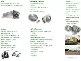
General purpose fittings • BSP and Hose taper and parallel fittings • Nickel plated brass construction • Adaptors • Connectors • Reducers • Expanders • Bulkheads • Tees • Elbows • Unions • Hose connectors • Banjos
Function fittings • Pneumatic sensor • Senses the falling exhaust pressure in an actuator and sends a signal when it has stopped • Blocking • Activated by removing a pneumatic pilot signal to block flow one way • Pressure reducing • Placed in the line to one end of a cylinder to reduce pressure 2 1
Fittings Taper male threads comply with ISO 7 (BS 21) and are designated by R 1/8 , R 1/4 , R 3/8 ,R 1/2 etc. Parallel male and female threads comply with ISO 228 (BS 2779) and are designated G1/8 , G 1/4 , G 3/8 , G 1/2 etc. Parallel metric threads are to ISO 261 (BS3643) designated M5x1, M10x1, M12x1.5, etc. Ports The ports in components such as cylinders and valves are parallel and comply to ISO 228 (BS2779) these are designated G 1/8 , G 1/4 , G 3/8 , etc. Parallel metric threads are to ISO 261 (BS3643) designated M5x1, M10x1, M12x1.5, etc. Thread standards (Europe)
Fittings Dryseal threads are taper male threads NPTF “National (American) Standard Pipe Taper Fuel and Oil” Sizes show TPI (threads per inch). The most popular range for industrial pneumatics are 1/8 -27, 1/4 -18, 3/8 -18,1/2-14, 3/4 -14 Ports The ports in components such as cylinders and valves are NPTF. This provides a male taper to female taper joint. NPSF and NPSI parallel female threads also allow connection with male taper NPTF fittings Thread standards (USA)
Sealing the thread • Parallel threaded fittings seal on a washer between the fitting and the face of the component’s port. The surround to the port is usually spot face machined • Taper threaded fittings rely on a lightly wedged fit and use sealant between the threads of the fitting and port
Taper to parallel • Taper fittings are made smaller in diameter as there is no bearing surface required for a washer • Taper fittings do not require the port to be spot faced so are suitable for ports in unmachined components and ports at an angle to their surface • By manufacturing to selected tolerances taper fittings are successfully used with parallel ports • This combination is very popular in many sectors of the pneumatics industry • Fittings must not be over tightened, particularly for ports in thin wall cast material as there is a risk of cracking the casting
The safe working pressure for the majority of pneumatic systems is 10 bar maximum with some components up to 16 bar maximum Most fittings will be safe at pressures in excess of these but obtain advice Plastic tubing is limited by wall thicknes and operating temperature Metal tubing has a higher rating Pressure Max from Vacuum Pneufit 18 bar * FleetFit 10 bar WeldFit 18 bar * Plasfit 10 bar Limited by plastic tube Push-on 9 to 11 bar Compression 15 to 28 bar* If tubing allows andnot including regulating banjos which are 10 bar Working pressure ranges Tubing details
Temperatures are generally limited by the plastic and rubber parts of a fitting and the tube material For extreme temperatures use compression fittings and metal tube. Also choose taper threads Where parallel threaded fittings are supplied with plastic washers the temperature is limited to- 40OC to 70OC Push- in Range Pneufit -200C to 700C Plasfit 00C to 700C Fleetfit - 400C to 1000C Weldfit - 300C to 700C Push- on 24 Series 0OC to 70OC Compression fittings with metal tube at 10 bar - 40 to +100OC BSP and Hose limited by tube or hose Working temperature ranges
Higher temperatures OC 30 40 50 60 80 Pressure adjustment factor 0.83 0.72 0.64 0.57 0.47 Pressure rating Plastic tube O/D mm 4 5 6 8 10 12 14 16 22 28 bar maximum Polyamide (PA) 28 31 25 19 24 18 15 18 15 15 Polyurethane (PU) 10 11 10 9 9 9 Pressure values are for a temperature range -40 OC to +20 OC For compressed air above 16 bar consult our technical service
OC 100 150 175 200 Annealed 0.97 0.82 0.63 0.43 Half Hard 0.95 0.88 0.54 0.29 Pressure rating Copper and steel tube O/D mm 4 5 6 8 10 12 16 22 28 bar maximum Copper Annealed 128 138 112 81 64 81 59 53 41 Copper Half Hard 193 208 218 157 150 122 89 81 62 Steel 300 250 195 160 Pressure values are for a temperature range -40 OC to +50 OC For compressed air above 16 bar consult our technical service Pressure adjustment factors