Download
1 / 54
550 likes | 724 Vues
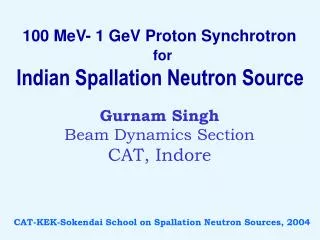
100 MeV- 1 GeV Proton Synchrotron for Indian Spallation Neutron Source. Gurnam Singh Beam Dynamics Section CAT, Indore. CAT-KEK-Sokendai School on Spallation Neutron Sources, 2004. RFQ 4.5 MeV. 100 MeV Linac. Linac to PS Transfer Line. H- Source. 100 MeV – 1 GeV PROTON

E N D
100 MeV- 1 GeV Proton Synchrotron for Indian Spallation Neutron Source Gurnam Singh Beam Dynamics Section CAT, Indore CAT-KEK-Sokendai School on Spallation Neutron Sources, 2004
RFQ 4.5 MeV 100 MeV Linac Linac to PS Transfer Line H- Source 100 MeV – 1 GeV PROTON SYNCHROTRON (PS) Target PS to Target Transfer Line BASIC LAYOUT OF INDIAN SPALLATION NEUTRON SOURCE
Outline: • Preliminary design aspects of Rapid Cycling Proton Synchrotron • Linac to Synchrotron Transfer Line
Preliminary design aspects Of Rapid Cycling Proton Synchrotron
Key parameter in a spallation source Beam Power Pbeam = q.Np.E .R = I.E • Pbeam:Beam power (W) at target • q :Charge on proton (C) • Np :No. of protons in ring • E :Final proton energy (eV) • R :Repetition rate (Hz) • I :Average current at target (A)
To increase the beam power Two Ways • Increase beam energy • Large machine, big cost • Increase beam Current • Severe space charge • Collective beam instabilities Choose optimum energy & current
Accelerator choice Linac & RCS Full Energy Linac & Accumulator Ring • High power achievable but high cost • High injection energy means very tight beam loss control at injection • High injection energy, so more heating of injection foil • Low injection energy, thus more space charge problem • Rapid acceleration, means powerful RF systems • Ceramic chamber
Indian Spallation Neutron Source • 100 MeV Linac & RCS based • Beam power :100 kW • Final energy of the beam : 1 GeV • Average current : 100 A • [@ 25 Hz Repetition Rate] 2.41013 protons in synchrotron
Design Considerations 1. Injection energy 100 MeV The first estimation of current in the synchrotron is made by space charge tune shift. => For the required N, the tune should not cross any dangerous resonances. Thus tune should have sufficient room for movement. In our design, allowable tune shift taken as 0.2.
For decreasing the tune shift (for enhancing the average current handling capability of the synchrotron) * Increase the injection energy => Increase the cost of Linac. * Decrease the N and increase the repetition rate, so that average current remains same => Constraints from technology and frame overlap in time of flight type experiments. *Increase the bunching factor at injection => Deciding factor of RF programme of the machine.
2. Beam loss control Beam loss control is of major concern in the high intensity machines. 1W/m is the allowable limit of uncontrolled loss for hands on maintenance. => @ injection, average beam power 10 kW Uniform loss on whole length of ring gives the upper most limit: 2% allowed uncontrolled loss. => Thus for controlled loss, betatron and momentum collimators needed.
3. Sufficient space Large dispersion free straight sections are needed for 1) RF systems. 2) Betatron collimators 3) Injection systems 4) Extraction system Apart from these, other systems which should be accommodated in the ring are diagnostic devices, vacuum pumps, correctors etc. 4. High tune for working well below the transition
Options for the lattices Many lattice configurations can fulfill these requirements: For making an arc with achromatic conditions 1. FODO with Missing dipole scheme (IPNS, KEK-JAERI etc.) 2. Achromat design (eg. SNS) Obtaining the long straight dispersion free sections 1. FODO 2. Doublet/ Triplet structures
Lattice for the ISNS FODO structure: Simple, smooth variation of beta function means less prone to errors. Missing dipole for the dispersion matching Four superperiods The four long straight sections will be used for the injection system, collimators (beam collimatoss), RF- system and extraction system respectively. Four superperiods have better stability for structure resonance than the three period structure.
Qd1 Qf3 Qd1 Qf1 Qf2 Qd2 Qf1 ARC SECTION One period • Half-cell length of FODO: 4.425 m • Total cells in arc: 4 (one period) • Total straight section cells: 2 (one period) • Quadrupole families: 5 (3f & 2d) • Length of the period: 53.1 m • Length of long straight: 43.875=15.5 m
Choice of tune 90 phase advance per cell requires a tune of 6.0, so the tune of the machine is kept near 6.0. In horizontal plane, it is higher than the 6.0 and in vertical plane it is on the lower side. But it has wide tunability range and it can be operated at split and un-split working points.
X- y=0 2X- y=8 3X- y=12 y 7 X- y=1 (6.3, 6.3) X+2 y=20 (7.3, 6.3) 6 • • • (6.88, 5.88) X+3 y=24 5.5 3X+y=28 2X+2 y=24 5 3X=20 X+2 y=16 4 x 7 5 6 8 6.5 Structure & half integer resonance diagram ( upto 4th order) Shaded region is the space for different tune options
* Further selection depends on imperfection resonance The lattice can have various tune points in these regions. Primarily selected tune is 6.88 and 5.88 [other options are 6.3, 6.3 and 7.3, 6.3 (higher tunes)]. Tune is far away from resonance up to 3rd order. Tune drift of –0.2 (due to space charge) does not hit any resonance up to 3rd order.
Preliminary tracking results with sextupoles (without error) Vertical phase space, 5000 turns Horizontal phase space, 5000 turns Initial co-ordinates are chosen corresponding to maximum displaced particle in both the planes with 1% p/p. Further optimization needed in sextupoles for vertical plane.
H - Injection 500 s ( 300 turns ) pulse length of H- ions from 100 MeV linac to be injected through a stripping foil. Constraints imposed by Liouville’s theorem on conventional multi-turn injection do not apply in this case. possible to inject a large number of turns.
Goals Of Injection To fill transverse acceptances ( x = y = 300 mm mrad) in K-V distribution uniform filling avoid excessive space charge forces referred as injection painting
Injection Paintings Horizontal Phase Space : Variable Bump by four bump magnets located in a long straight section Angle of Injection Peak of the bump at the stripping foil Minimum number of traversal of beam through the foil
Partially stripped particles H0 do not pass through high magnetic field ( centre of QD ) Sripped H- (Magnetic field) unwanted halo formation around circulating particles
Orbit Bump and its Slope at the Location of Stripping Foil (Injection Point) vs Injection Turn Number
Amplitude of Betatron Oscillations of Injected Particles with Turn Number During Injection
Striping Foil • Thickness of the foil: (High stripping efficiency ) At 100MeV 60g cm-2 is adequate • Foil materials: Polyparaxylene,carbon or Aluminium oxide
Beam loss and Collimators The lattice should accommodate the collimators (betatron and momentum) for controlled loss. At injection only 2% particle loss is allowed (if distributed uniformly all over the length) in the ring. Key parameter in collimator design: Phase advance between primary and secondary collimators and their apertures
Collimators remove the Halo from the beam at the predefined locations. • The first collimator scatters the halo particles, with low impact parameter. Due to scattering, the amplitude increases and these are collected at secondary collimator, which is placed at a proper phase advance.
Proper phase and critical kick is given by n1 and n2 are the apertures of primary and secondary in terms of beam size. The critical kick is Phase difference between primary and secondary collimator X – Plane: 158 and n2/n1=1.08 Y – Plane: 144 and n2/n1=1.20
Material choice in collimators • Two Effects: • When a proton traverse through a primary collimator, it loses energy. If this loss is high, particle may be out of bucket or longitudinal acceptance. (Acceptance of ring 1%) • The primary collimator has to give a large kick, so protons hit the secondary collimator with large impact parameter. This kick is largely imparted through the multiple Coulomb scattering.
The first effect demands a very thin collimator, which does not cause the much energy loss. The second effect demands a high Z material. Thus choices are among Pt, W etc. Other requirements are good thermal conductivity, high melting point, good polishing capability, radiation damage. As high Z has the shower effects, which is drawback. Therefore, for proper choice of material and optimization of its thickness, simulation studies are essential.
y-plane x-plane Tentative locations of betatron collimators In next period to injection. Phase difference between primary and secondary collimator X – Plane: 158 and n2/n1=1.08, beam sizes at the collimators: 4.2cm, 3.8 cm, 3.2 cm Y – Plane: 144 and n2/n1=1.20, beam sizes at the collimators: 3.8cm, 5.6 cm, 3.6 cm
Tentative locations of momentum collimators In arc next to injection system. Phase difference between primary and secondary collimator X – Plane: 150 and n2/n1=1.15
Preliminary beam diagnostic requirements 48 Beam position monitors ( one @ each quadrupole). Beam loss monitors distributed all over the ring. Beam profile monitors. Current monitors (Average and Pulse).
Linac to Synchrotron Transfer Line
• Design Philosophy • To match the beam parameters from the linac output to synchrotron injection point. • To provide the adequate space for installation of various components, as 1.RF cavity for energy jitter correction. 2.Diagnostic elements (Profile monitors, Current monitors, Beam position monitors and Beam loss monitors). 3.Dump line. 4.Bumpers for injection painting. • To install collimators for control of beam loss.
Optics parameters of Transfer Line Matching section 4 Quads Matching section 4 Quads 1 FODO Achromat 2 FODO
Primary collimator Secondary collimator X Secondary collimator Y RF Cavity