Download
1 / 13
130 likes | 316 Vues
Requirements for a bolometer prototype at the 30m telescope. S.Leclercq 23/04/2009. The IRAM 30m telescope (MRT, Pico Veleta). In the Sierra Nevada (Spain), at 2900m. 4 atmospheric windows available: 3, 2, 1, 0.9 mm . Primary mirror diameter = 30m, secondary = 2m.

E N D
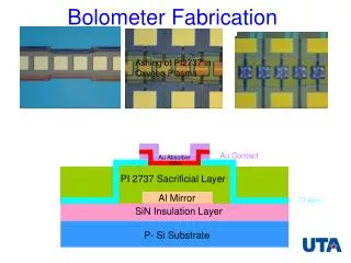
Requirements for a bolometer prototype at the 30m telescope S.Leclercq 23/04/2009
The IRAM 30m telescope (MRT, Pico Veleta) • In the Sierra Nevada (Spain), at 2900m. • 4 atmospheric windows available: 3, 2, 1, 0.9 mm. • Primary mirror diameter = 30m, secondary = 2m. • F=f/D ~ 10 diffraction beam ~ 10”. FOV ~ 4’. • Cassegrain with Nasmyth focus (beam along elevation axis). • Current bolometer instrument: MAMBO 2: 117 pixels (feedhorns), FOV=3.5’, NEFD ~ 40 mJy·s1/2.
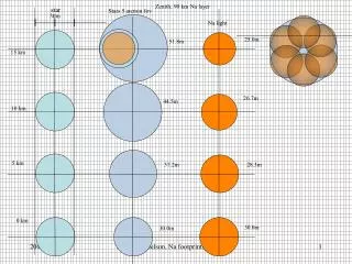
Bands available at the 30m ATM opacity model at Pico Veleta, for winter (260K) and summer (300K) with good weather (1mm of water vapour) and bad weather (7mm) Centre of the bands for a maximal width, and corresponding size of the FWHM diffraction pattern
Optical chain efficiency and real beam r = (/2) (/D) = diffraction space natural radius I = relative intensity example: Airy diffraction pattern L = relative power Definitions and efficiency measurements Aperture efficiency = relative flux losses from the optical chain: ea = Ae /A= Pcollected(0)/Pincident Beam efficiency = relative power at the main beam radius (1stdark ring of the Airy beam): Beff = L(rmb) Forward efficiency = relative power from the 2p steradian plane in front of the telescope: Feff = L(r2p) Surface deformations on the main dish alter the diffraction pattern. Parameters: steepness factor (R), aperture efficiency at long wavelength (e0), RMS deformations height (sh=55m), correlation lengths (3 components: de= [2.5 1.7 0.3] m). Ruze law : ea(l)=e0 exp(-S(sh 4pR/l)2) Components of the aperture efficiency from measures conducted in 2007 [C.Thum]: e0 =ohmic losses (total all mirrors 89%) * blockage (98%) * 13dB taper spillover (92% (ground emissivity = 30%)) * 13dB taper illumination (87%) * alignment & leakage (97%) * Ruze @ 86GHz (95%)= 65 % Other efficiencies (for simulations): cryostat filters tf 70%, detector efficiency and others: to = 85%
Relative powers 92 90 86 75 % Feff= 61 45 35 16 ea= % 73 54 42 19 % Beff= Optical chain efficiency and real beam Beams Dash lines = Empirical Gaussians Solid lines = Antenna Tolerance Theory q = radius in powers of ten times a 10dB edge taper main beam q = radius in units of a 10dB edge taper main beam Graphics Legend of the curves: Airy diffraction pattern Real beam l=3.4mm Real beam l=2.0mm Real beam l=1.3mm Real beam l=0.86mm
Pixel types Central n: Bandwidth: 40 95 260 530 170 420 1100 2300 Simulations for an optimal bolometer array Bands 0.5Fl square bare multimodes pixels in a filled array 2Fl round 10dB edge monomode feedhorns in a compact array Extended source Point source Global efficiency < 50 % ~ ea/4 < 65 % ~ ea 540 1400 3600 7300 2400 5700 16000 32000 Number of pixels for 2 fields of view Square grid: Hexagonal grid: FOV = (4.8'10')
Collected power Noise Equivalent Power Simulations for an optimal bolometer array Matrices below: columns = weather condition: good (1mmwv) / bad (7mmwv) ; lines = bands: 3mm / 2mm / 1mm / .9mm Background sources: atmosphere, ground, telescope, cryostat. Benchmark sources: Jupiter, 1KRJ extended, 1mJy point (Jy = 10-26 W/(m2Hz) 0.5 Fl bare pixel 2 Fl feedhorn Convenient noise unit: nu = 10-17 W/Hz1/2 Summing Nb pixels RN=NEPNb/NEP1 Shot noise: Bunching noise: Total: Best pixel noise: NEPbkgTb / 6 NEPpix ~<1nu 0.5 Fl bare pixel 2 Fl feedhorn NEPbkgTh / 6 NEPpix ~ few nu
Noise Equivalent Temperature Noise Equivalent Flux Density Simulations for an optimal bolometer array (Nb = number of pixels, obs = observing mode efficiency : OTF =1.6, OnOff =2.1) (no pixels efficiency hNb in P1KRJ) (pixels efficiency hNb inside P1mJy) 4 0.5 Fl bare multimodes pixels 2 Fl monomode feedhorn Integration time to detect a source at S/N=s: t = 0.5(shobsNEP/P)2 = (sNET/T)2 = (sNEFD/F)2 Extended source T=100K: Point source (Ps<< background): Mapping speed comparison: Filling ratio bare square grid vs feed hexagon grid: Nb/Nh=13.9 4 bare pixels vs 1 feedhorn Comparison with Griffin's: with shot noise only my results ~1.3x more favorable to feedhorns (assumptions on throughput, efficiencies, filters, geometry) ; including bunching noise my results ~2-3x more favorable to bare pixels (multimode vs monomode) ! Time & speed simulations in this presentation assume no sky noise & no confusion
Expectations for the future science grade instrument • At least 2 colors (bands / channels) • Current preferred colors: l = [1.25 ; 2.05] mm (n = [146 ; 240] GHz) • Total efficiency per pixel > 40% ? • Background limited instrument : NEPpix<NEPbkg/6 (in previous slide NEPbkg given for hpix=90%, if pixel less efficient NEPbkg lower, hence factor 6 rather than 3) • Sensitivity: ~0.5mK/Hz1/2 & ~3mJy/Hz1/2 @ 1mmwv, and stay <1mK/Hz1/2 & <10mJy/Hz1/2 in a large dynamic range (15-150 KRJ background) • Preference for fully sampling (0.5Fl) pixels (advantage for mapping) ? • Preference for filled array (best to fight anomalous refraction in sky noise) • Field Of View 6' • Preference for multiplexing since FOV>6' 100s - 1000s pixels • Negligible sensitivity to stray-lights • Cost < 6M€ including (5M€ as dedicated time <1M€ cash)
Requirements to test a prototype at the 30m • Working array with at least 32 pixels in a single attached block or area. • Array fully characterized with lab tests: pixels + multiplexing. • Agreement by collaborators on the procedures to measure pixel noise performance and sensitivity in lab (noise spectra, black body response, etc.). • Sensitivity for useful tests and first light science: pix0.5? &NEPinst1F<1016W/Hz1/2. • Translation of lab to on site performance must be worked out (NEEL & IRAM), my rough estimate for summer time (5mmwv): (tot_ext~25%, tot_pix~10%) & /c~30% good weather: NET~0.5mK/Hz1/2 , NEFD~8mJy/Hz1/2 , t10mJy@3s ~ few seconds. • Preliminary frequency range of optimization is 1-20 Hz, noise spectra will be taken for a statistically significant number of pixels. • Optical measurements showing that the internal optics is working according to the design goals: valuable illumination of the telescope and no stray-light (optical filters ready, XY maps with chopper, secondary lobes). • Instrument control & mapping software OK to avoid down time during telescope tests. • Only hardware successfully tested in laboratory can be employed at the telescope. • List of sources for observations prepared and agreed in advance.
Constraints for a prototype at the 30m • The prototype components must fit in the available space in the receiver cabin. • The instrument must fit on the anti-vibration table, which can't be moved for such tests. • The only structures than can be removed are the MAMBO 2 elements on the anti-vibration table, in particular the M5-M6 tower must stay in place.
Constraints for a prototype at the 30m • No interference with telescope observation during time not allocated to the prototype. • For communication between instrument and control room use the 1Gb shared ethernet link, (the availability of a separate twisted pair cable that can run at 100Mb/s is not warranted yet). • Use a special process to request "real time " position of the antenna via ethernet ; more complete information can be written in FITS files every minute. • A maximum of 8 external persons at a time can be lodged at the telescope. • Cryogen needs must be known several weeks in advance.
Schedule and expectations for the summer 2009 prototype test • June: lab test at Neel in collaboration with IRAM (MR/SL/KS), for a potential green light at the end of the month (see requirements). • July: IRAM deliver M7 & M8 (HDPE lenses ?) to Neel. Optical tests. • July: agreement on the list of sources for the observation with the prototype. • August 4-25 or August 11-31: tests at the 30m • Week 0: all hardware shipped to the telescope. • Week 1: mounting and test on site without the telescope beam (the prototype can be mounted in the receiver cabin only the 3 last days of this week). • Week 2: day time use of the telescope beam. • Week 3: night time use of the telescope beam. • Week 4: dismount the prototype. • Expectations: • For green light to week 3: at the end of week 2 observation of selected sources must be successful. • Objective: observation of ~10mK / ~100mJy sources in few seconds...