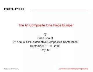
The All Composite One Piece Bumper
310 likes | 574 Vues
The All Composite One Piece Bumper. by Brian Knouff 3 rd Annual SPE Automotive Composites Conference September 9 – 10, 2003 Troy, MI. Introduction. Delphi Composites Center of Excellence set up to Affordably Integrate Composites into Transportation Industry ~ 1999

The All Composite One Piece Bumper
E N D
Presentation Transcript
The All Composite One Piece Bumper by Brian Knouff 3rd Annual SPE Automotive Composites Conference September 9 – 10, 2003 Troy, MI
Introduction • Delphi Composites Center of Excellence set up to Affordably Integrate Composites into Transportation Industry • ~ 1999 • Stemmed from columns work done in Salt Lake City • Cost penalty realized • Other benefits crucial • Class 8 truck market benefits: • Less road wear and tear • Fewer loads for those vehicles which gross out • Less traffic • Less pollution • Less maintenance for those which cube out • Better mileage
Challenging Sacred Cows • Glass not Stiff Enough to Replace Steel • Carbon Too Expensive • Composites Can’t be Attached • adhesives work in some applications • Composites Display Poor Fatigue Properties • Process Cycle Time Too Long
Strategy • Utilize Advanced Modeling Techniques to Optimize Composite Designs • Work with Government Labs, Universities and Commercial Partners to Investigate Alternative Precursors/Carbonization Techniques • Develop Novel Processes with Emphasis on Reduced Cycle Times • Work with Suppliers to Reduce Material Costs at High Volumes
First Application • Aftermarket Class 8 Bumper
Background • Metal bumpers account for about half of the market
Background • Plastic bumpers make up the balance SMC Thermo Plastic Polyolefin ABS Alloy FRP
Design Requirements • Natural Frequency >50 Hz • Deflect <0.5 inches with 300 lb downward load at end • represents large person stepping on bumper to clean hood, etc… • Deflect <0.5 inches with 50 lb forward load at end • represents hitting small object, windloads, etc… • Aesthetically pleasing with carbon fiber visible • Class A surface • Mass savings > 50%
Conclusions • Composite bumpers can be designed to replace either steel or plastic bumpers • Composite bumpers can be commercialized in today’s market at high volumes (competitive piece price) • Versus Steel • lighter • increased design flexibility • lower tooling costs • Versus Plastic • stronger • stiffer • fewer parts (1 versus 40) • lower tooling costs
Old Production • Very large volumes • Huge investments in tooling • Every part the same • Part/Plant redesign every 10 years or so
New Production • Low to medium volumes as well as high volumes • Minimal investments in tooling • Parts constantly changing • Plants fluid (modular) and lean • Opportunity for structural polymer composites
Aftermarket Class 8 Bumper Less than 40 lbs. Nf~20 Hz 1 piece construction Charcoal gray or black color No visible fibers on front face Textured, non-painted surface Production Intent
Optimized for Natural Frequency Topology dictated areas of critical mass. Product Design Math-based Optimization Optimize with design responses, variables, constraints, and objectives Grid can be made dynamic Typical design parameters include: thickness fiber type fiber orientation fiber volume fraction shape Part Design
Process Development • Low-cost tooling • not steel or aluminum • Easy preform construction • no spray or robotic tooling • few piece construction • template cutting • switch to more automated process in production • Minimize equipment $ • vacuum infusion versus RTM • Experience showed that stitched fabrics too tight to vacuum infuse • needed to use rollers for GATS bumpers
Production Process • Vacuum Infusion • Closed 2-sided mold • No injection pressure • Vacuum at exhaust pulls resin through inlet and through fabric
Precut Preform The pattern is cut from a single sheet of 3WEAVE fabric
Tucking Preform Single layer of 54oz is conformed into the mold
Micrography • Microscopic analysis displays: • Excellent wetout • Absence of voids • Good fiber distribution • Barrier coat thickness
Today Place several materials into mold Form materials into mold Process materials into mold Remove part Trim and package Ship Future Place net-shape preform into mold Process into part Remove part Ship Make A Part