PRESS WORK
PRESS WORK. INTRODUCTION. INTRODUCTION. Press working is a method of mass production involving the cold working of metals , usually in the form of thin sheet or strip. Press working is one of the extensively employed methods of fabricating parts of intricate shapes with thin walls.


PRESS WORK
E N D
Presentation Transcript
PRESS WORK INTRODUCTION
INTRODUCTION • Press working is a method of mass production involving the cold working of metals , usually in the form of thin sheet or strip. • Press working is one of the extensively employed methods of fabricating parts of intricate shapes with thin walls. • Press working processes make use of large forces by press tools for a short time interval which results in cutting or shaping the sheet metal.
Since, press working does not involve heating of the parts, close tolerances and high surface finish can be obtained on the part. • Press worked parts does not require any machining also. • Since presses can produce components at fairly fast rates, the unit cost of labor for operating the press is fairly low.
A disadvantage, however, associated with (cold) presswork is that because of work hardening metal is less deformable due to its higher resistance. • Press working forces are set up, guided and controlled in a machine referred to as PRESS
PRESSES FOR SHEET METAL WORKING • Classification of presses. • Types of presses for sheet metal working can be classified by one or a combination of characteristics, such as 1) Source of power, 2) Number of slides, 3) Type of frame and construction, 4) Type of drive, and intended applications.
Classification on the basis of source of power. • 1) Manually operated (fly) press. 2) Power operated presses.
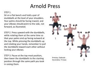
Manual Presses. These are either hand or foot operated through levers, screws or gears. A common press of this type is the arbor press used for assembly operations. • Mechanical presses. These presses utilize flywheel energy which is transferred to the work piece by gears, cranks, eccentrics, or levers.
Hydraulic Presses. These presses provide working force through the application of fluid pressure on a piston by means of pumps, valves, intensifiers, and accumulators. • These presses have better performance and reliability than mechanical presses.
Pneumatic Presses. These presses utilize air cylinders to exert the required force. • These are generally smaller in size and capacity than hydraulic or mechanical presses, and therefore find use for light duty operations only.
Classification on the basis of number of slides. • Single Action Presses. A single action press has one reciprocation slide that carries the tool for the metal forming operation. • The press has a fixed bed. It is the most widely used press for operations like blanking, coining, embossing, and drawing.
Double Action Presses. A double action press has two slides moving in the same direction against a fixed bed. • It is more suitable for drawing operations, especially deep drawing, than single action press. For this reason, its two slides are generally referred to as outer blank holder slide and the inner draw slide.
The blank holder slide is a hollow rectangle, while the inner slide is a solid rectangle that reciprocates within the blank holder.. • The blank holder slide has a shorter stroke and dwells at the bottom end of its stroke, before the punch mounted on the inner slide touches the work piece. In this way, practically the complete capacity of the press is available for drawing operation.
Another advantage of double action press is that the four corners of the blank holder are individually adjustable. • This permits the application of non uniform forces on the work if needed. • A double action press is widely used for deep drawing operations and irregular shaped stampings.
Classification on the basis of frame and construction. • Arch Frame Presses. These presses have their frame in the shape of an arch. These are not common. • Gap Frame Presses. These presses have a C-shaped frame. These are most versatile and common in use, as they provide un obstructed access to the dies from three sides and their backs are usually open for the ejection of stampings and / or scrap.
Straight Side Presses. These presses are stronger since the heavy loads can be taken in a vertical direction by the massive side frame and there is little tendency for the punch and die alignment to be affected by the strain. The capacity of these presses is usually greater than 10 MN. • Horn Presses. These presses generally have a heavy shaft projecting from the machine frame instead of the usual bed. This press is used mainly on cylindrical parts involving punching, riveting, embossing, and flanging edges
Press Selection • Proper selection of a press is necessary for successful and economical operation. • Press is a costly machine, and the return on investment depends upon how well it performs the job. • There is no press that can provide maximum productivity and economy for all application so, when a press is required to be used for several widely varying jobs, compromise is generally made between economy and productivity.
Important factors affecting the selection of a press are size, force, energy and speed requirements • Size. Bed and slide areas of the press should be of enough size so as to accommodate the dies to be used and to make available adequate space for die changing and maintenance. • Stroke requirements are related to the height of the parts to be produced. Press with short stroke should be preferred because it would permit faster operation, thus increasing productivity. • Size and type of press to be selected also depends upon the method and nature of part feeding, the type of operation, and the material being formed.
Force and Energy. Press selected should have the capacity to provide the force and energy necessary for carrying out the operation. • The major source of energy in mechanical presses is the flywheel, and the energy available is a function of mass of flywheel and square of its speed. • Press Speed. Fast speeds are generally desirable, but they are limited by the operations performed. • High speed may not, however, be most productive or efficient. Size, shape and material of workpiece, die life, maintenance costs, and other factors should be considered while attemping to achicve the highest production rate at the lowest cost per piece.
Mechanical versus Hydraulic Presses • Mechanical presses are very widely used for blanking, forming and drawing operations required to be done on sheet metal. • For certain operations which require very high force, for example, hydraulic presses are more advantageous. • Table 7.1 gives a comparison of characteristics and preferred application of the TWO types of press.
PRESS WORKING DIES • DIE AND PUNCH • A typical die and punch set used for blanking operation is shown in Fig 8.1. • The sheet metal used is called strip or stock. • The punch which is held in the punch holder is bolted to the press ram while die is bolted on the press table. • During the working stroke, the punch penetrates the strip. • On the return stroke of the press ram, the strip is lifted with the punch, but it is removed from the punch by the stripper plate.
The stop pin is a gage and it sets the advance of the strip stock within the punch and die. • The strip stock is butted against the back stop acting as a datum location for the centre of the blank. • The die opening is given angular clearance to permit escape of good part (blank). • The waste Skelton of stock strip, from which blanks have been cut, is recovered as salvaged material
The clearance angle provided on the die (Fig 8.1) depends on the material of stock, as well as its thickness. • For thicker and softer materials generally higher angular clearance is given. • In most cases, 2 degree of angular clearance is sufficient. The height of cutting land of about 3 mm is generally sufficient.
CLEARANCE • In blanking operation , the die size is taken as the blank size and the punch is made smaller giving the necessary clearance between the die and the punch. • Die size = blank size • Punch size = blank size - 2 x clearance • Clearance = k . t .τ • Where ‘τ’ is the shear stress permissible of material, t is the thickness of sheet metal stock, and k is a constant whose value may be taken as 0.003.
In a Punching operation (piercing), the following equations hold. • Punch size = blank size • Die size = blank size + 2 x clearance • Clearance = k . t . τ
TYPES OF DIES • The components generally incorporated in a piercing or blanking die are shown in Fig 8.3. This Figure shown the die in the conventional closed position. The die set is made up of the punch holder which is fastened to the ram of the punch press and the die shoe which is fastened to the bolster plate of the punch press.
Generally, the punch is fastened to the punch holder and aligned with the opening in the die block. Fig 8.2 shows one type of stripper plate and push off pins. • The stripper holds the scrap strip so that the punch may pull out of the hole. • The push off pins are needed to free the blank in instances where the material strip clings to the bottom of the punch. This may be necessary for thin material, or where lubricants are used on the material.
Inverted die (Fig 8.3) is designed with the die block fastened to the punch holder and the punch fastened to the die shoe. • During the downward stroke of ram, the blank is sheared from the strip. • The blank and shedder are forced back into the die opening, which loads a compression spring in the die opening . • At the same time the punch is forced through the scrap strip and a spring attached to the stripper is compressed and loaded.
On the upstroke of the ram, the shedder pushes the blank out of the die opening and the stripper forces the scrap strip off the punch. The finished part (blank) falls, or is blown, out the rear of the press.
Compound die (Fig 8.4) combines the principles of the conventional and inverted dies in one station. • This type of die may produce a work piece which is pierced and blanked at one station and in one operation. • The piercing punch is fastened in the conventional position to the punch holder. Its matching die opening for piercing is machined into the blanking punch. • The blanking punch and blanking die opening are mounted in an inverted position. • The blanking punch is fastened to the die shoe and the blanking die opening is fastened to the punch holder
Progressive dies are made with two or more stations arranged in a sequence. • Each station performs an operation on the work piece, or provides an idler station, so that the work piece is completed when the last operation has been accomplished. • Thereafter each stroke of the ram produces a finished part. Thus after the fourth stroke of a four station die, each successive stroke will produce a finished part. • Operations which may be carried out in a progressive die are piercing, blanking, forming, drawing, cut off, etc.
The list of possible operations is long. The number and types of operations which may be performed in a progressive die depends upon the ingenuity of the designer. • Fig 8.5 shows a four station progressive die. • The die block is made up of four pieces and fastened to the die shoe. This permits easy replacement of broken or worn die blocks. • The stock is fed from the right and registers against a finger strop (not shown). The first stroke of the press Fig 8.5(a) produces a square hole and two notches. These notches form the left end of the first piece.
During the upstroke of ram, the stock is moved to the next station against a finger stop (not shown). • The stock is positioned for the second stroke. • The second station is an idler, Fig 8.5(b). The right end of the first piece, the left end of the second piece, and a second square hole are pierced.
The ram retracts and the scrap strip is moved to the third station against an automatic stop, Fig 8.5(c). • This stop picks up the notched V and positions the scrap strip. • The third stroke of the ram pierces the four holes as shown in Fig 8.5(c). • The fourth stroke, Fig 8.5(d), cuts off and forms the radii at the ends of the finished piece. • Thereafter every stroke produces a finished part, Fig 8.5(e).
Press Working Materials • Mild steel, copper and brass are the chief materials used in press work operations. • The greatest production is from steel strip or sheet metal. Steels for press work may be annealed, dead soft, soft, bright annealed, quarter hard, half hard, three-quarter hard, and extra spring hard; of these the harder grades are used for easy blanking and punching, and dead soft for deep drawing.
Brass for press work operations may be annealed, quarter hard, half hard, hard, extra hard etc. Cartridge brass ( 70% Cu and 30% Zn) is used extensively for deep-drawing operations. • Other press work materials are alloy steels, electrical steels, stainless and heat- resisting steels, wrought aluminum alloys, wrought magnesium alloys, Zinc and zinc alloys, titanium and its alloys etc.