Download
1 / 13
130 likes | 244 Vues
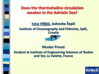
Study on Indicator Variograms using Split Beam Echosounder in the Adriatic Sea, analyzing NASC data and setting threshold values for survey design. Comparison of data collected for Engraulis encrasicolus and Sardina pilchardus over three years (2008-2010).

E N D
AcousMed Heraklion, Crete 12 - 16 December 2011 Indicator Variograms for Survey Design Estimation in the Adriatic Sea Claudio Vasapollo c.vasapollo@an.ismar.cnr.it Iole Leonori i.leonori@ismar.cnr.it Andrea De Felice a.defelice@ismar.cnr.it
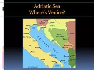
Study Area & Data collection • Study area: Adriatic Sea • Years: 2008, 2009, 2010 • Target species: Engraulis encrasicolus, Sardina pilchardus (not shown) • Split Beam Simrad Echosounder EK 60 at 38 – 120 – 200 kHz • TS and Sv thresholds set to -80 dB for data logging and -70 dB (-60 dB depending on kind of echogram) for data processing • 8 - 10 nm inter-transect distance • EDSU was 1 nm • Min Bottom Depth 10m • Vessel speed : 9.5 knots • Data collection: day and night • Myriax Echoview for Echogram analysis
Relative densities Maps of relative NASC densities. Each circle is proportional to NASC values divided by the maximum value in the survey.
Cumulative Frequencies 10% of the data contributed for < 80% of the NASC values
Indicator Thresholds • I1 : 50% • I2 : 75% • I3 : 85% • I4 : 90% Thresholds have been selected as quantiles. No zeros nor extreme values deletions. P(z) is the proportion of NASC greater than z. z is the correspondent quantile value. • I1 : 50% • I2 : 75% • I3 : 85% • I4 : 90% P(z) : 50% P(z) : 25% P(z) : 15% P(z) : 10% Correspondent quantile values • 2008 • I1 : 483 • I2 : 894.5 • I3 : 1189.6 • I4 : 1483.6 • 2009 • I1 : 252.5 • I2 : 537.5 • I3 : 722.4 • I4 : 973.9 • 2010 • I1 : 270 • I2 : 662 • I3 : 942 • I4 : 1178
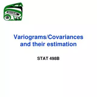
Normalized Isometric Variograms WLS automatic fitting method1: number of pairs as weight. Values Normalized for each single variance. 1Cressie, N. (1985). Fitting variogram models by weighted least squares. Mathematical geology, 17(5), 563–586.
Indicator Variograms: 2008 Ranges progressively decrease with increasing thresholds: smaller area of influence of high density spots
Indicator Variograms: 2009 The nugget increases (in percentage) with the increasing thresholds as well: the higher density spots are affected by more errors
Design Simulations: 2008 Halving and doubling the intertransect distance
Design Simulations: 2009 Halving and doubling the intertransect distance
Design Simulations: 2010 Halving and doubling the intertransect distance