Download

1 / 41
640 likes | 1.65k Vues
ERT 209 HEAT AND MASS TRANSFER FOR BIOPROCESS ENGINEERING Agitated Vessel. Agitation. Agitation refers to forcing a fluid by mechanical means to flow in a circulatory or other pattern inside a vessel.

E N D
ERT 209HEAT AND MASS TRANSFER FOR BIOPROCESS ENGINEERINGAgitated Vessel
Agitation • Agitation refers to forcing a fluid by mechanical means to flow in a circulatory or other pattern inside a vessel. • Mixing usually implies the taking of two or more separate phases, such as a fluid and a powdered solid or two fluids, and causing them to be randomly distributed through one another.
Purpose of Agitation 1. Blending of two miscible liquids, such as ethyl alcohol and water. 2. Dissolving solids in liquids, such as salt in water. 3. Dispersing a gas in a liquid as fine bubbles, - such as oxygen from air in a suspension of microorganisms for fermentation or for the activated sludge process in waste treatment. 4. Suspending of fine solid particles in a liquid, - in the catalytic hydrogenation of a liquid, solid catalyst particles and hydrogen bubbles are dispersed in the liquid. 5. Agitation of the fluid to increase heat transfer between the fluid and a coil or jacket in the vessel wall.
Equipment for Agitation • Three-blade propeller agitator • Paddle agitators • Turbine agitators • Helical-ribbon agitators
1. Three-blade propeller agitator FIGURE 3.4-1. Baffled tank and three-blade propeller agitator with axial-flow pattern: (a) side view, (b) bottom view
2. Paddle Agitators • often used at low speeds, between about 20 and 200 rpm. • Two-bladed and four-bladed flat paddles are often used, as shown in Fig. 3.4-2a. FIGURE 3.4-2. Various types of agitators: (a) four-blade paddle, (b) gate or anchor paddle, (c) six-blade open turbine, (d) pitched-blade (45 ) turbine.
At low speeds mild agitation is obtained in an unbaffled vessel. • At higher speeds, baffles are used - since, without baffles, the liquid is simply swirled around with little actual mixing. • The paddle agitator is ineffective for suspending solids - since good radial flow is present but little vertical or axial flow. • An anchor or gate paddle, shown in Fig. 3.4-2b, is often used. • It is used with viscous liquids where deposits on walls can occur and to improve heat transfer to the walls. • However, it is a poor mixer. Paddle agitators are often used to process starch pastes, paints, adhesives, and cosmetics.
3. Turbine Agitator • Turbines resemble of multibladed paddle agitators with shorter blades • used at high speeds for liquids with a very wide range of viscosities. • The turbines usually have four or six blades. • Figure 3.4-3 shows a flat six-blade turbine agitator with disk. • They are also useful for good gas dispersion; - the gas is introduced just below the impeller at its axis and is drawn up to the blades and chopped into fine bubbles. • Often a pitched-blade turbine with only four blades is used in suspension of solids.
Figure 3.4-3. Baffled tank with six-blade turbine agitator with disk showing flow patterns: (a) side view, (b) bottom view, (c) dimensions of turbine and tank.
4. Helical-Ribbon Agitator • used in highly viscous solutions • operates at a low rpm in the laminar region. • The ribbon is formed in a helical path and is attached to a central shaft. • The liquid moves in a tortuous flow path down the center and up along the sides in a twisting motion. • Similar types are the double-helical-ribbon agitator shown in Fig. 3.4-4b and the helical-screw impeller shown in Fig. 3.4-4c.
FIGURE 3.4-4. Other types of agitators: (a) high-efficiency, three-blade impeller (b) double-helical-ribbon, (c) helical-screw.
Agitated Vessel Power Used in Agitated Vessel • In the design of an agitated vessel, an important factor is the power required to drive the impeller. • Empirical correlations have been developed to predict the power required. • Reynolds number, is defined as: Where: Da = impeller (agitator) diameter (m) N = rotational speed (rev/s) ρ = fluid density (kg/m3) µ = fluid viscosity (kg/m.s) ---- Eq. (3.4-1)
Power consumption is related to fluid density ρ, fluid viscosity µ, rotational speed Nand impeller diameter Da by plots of power number Np versus • The power number is defined as: (SI) (English) Where P = power (J/s) or (W). In English units, P = ft.lbf/s. Figure 3.4-5 shows the power correlations for various impellers and baffles ----------------- Eq. (3.4-2)
Figure 3.4-5 Power correlations for various impellers and baffles (Geankoplis, 4th ed.)
Curve 1. Flat six-blade turbine with disk (like Fig. 3.4-3 but six blades); D/W = 5; four baffles each D/J = 12. • Curve 2. Flat six-blade open turbine (like Fig. 3.4-2c); Da/W = 8;four baffles each D/J = 12. • Curve 3. Six-blade open turbine (pitched-blade) but blades at 450 (like Fig. 3.4-2d); Da/W = 8; four baffles each Dt /J = 12. • Curve 4. Propeller (like Fig. 3.4-1); pitch 2D four baffles each Dt /J = 10; also holds for same propeller in angular off-center position with no baffles. • Curve 5. Propeller; pitch = Da four baffles each Dt /J = 10; also holds for same propeller in angular off-center position with no baffles. • Curve 6. High-efficiency impeller (like Fig. 3-4-4a); four baffles each Dt /J = 12.
Example 1 Power Consumption in an Agitator A flat blade turbine agitator with disk having six blades is installed in a tank similar to Fig. 3.4-3. The tank diameter Dt is 1.83 m, the turbine diameter Da is 0.61 m, Dt = H, and the width W is 0.122 m. The tank contains four baffles, each having a width J of 0.15 m. The turbine is operated at 90 rpm and the liquid in the tank has a velocity of 10 cp and a density of 929 kg/m3. a) Calculate the required kW of the mixer. b) For the same conditions, except for the solution having a viscosity of 100,000 cp, calculate the required kW.
Solution • For part (a) the following data are given: • Using Eq. (1), the Reynolds number is: • Using Curve 1 in Fig 3.4-5, since • Solving for P in Eq. (3.4-2) and substituting known values
For part (b) • This is the laminar flow region. From Figure 3.4-5, Np = 14. • Hence, a 10,000-fold increase in viscosity only increases the power from 1.324 to 3.71 kW.
Agitator Scale-Up • Scale-up the laboratory-size or pilot-size agitation system to a full-scale unit. • Scale-up procedure: • Calculate the scale-up ratio R. Assuming that the original vessel is a standard cylinder with DT1= H1, the volume is: The ratio of the volume is The scale-up ratio is then ----------------- Eq. (3.4-6) ----------------- Eq. (3.4-7) ----------------- Eq. (3.4-8)
Using this value of R, apply it to all of the dimensions in Table 3.4-1 to calculate the new dimensions. For Example, Da2= RDa1, J2 = RJ1… • Determine the agitator speed N2, to be used to duplicate the small scale results using N1. The equation is: Where n = 1 for equal liquid motion, n = ¾ for equal suspension solids and n = 2/3 for equal rates of mass transfer (which equivalent to equal power per unit volume, P1V1 = P2V2 ). This value of n is based on empirical and theoretical considerations. 4. Knowing N2, the power required can be determined using Eq. (3.4-2) and Figure 3.4-5. ----------------- Eq. (3.4-10)
Example 2 Scale up of Turbine Agitation System An existing agitation system is the same as given in Example 1a for a flat-blade turbine with a disk and six blades. The given conditions and sizes are DT1 = 1.83 m, Da1 = 0.61 m, W1 = 0.122 m, J1 = 0.15 m, N1 = 90/60 = 1.50 rev/s, ρ = 929 kg/m3and µ = 0.01 Pa.s. It is desired to scale up these results for a vessel whose volume is 3.0 times as large. Do this for the following two process objectives: a) Where equal rate of mass transfer is desired. b) Where equal liquid motion is needed.
Solution Since H1 = DT1 = 1.83 m, the original tank volume, Volume V2 = 3.0 (4.813) = 14.44 m3. Following the steps in the scale-up procedure, and using Eq.(3.4-8): The dimensions of the larger agitation system are as follows: DT2 = RDT1 = 1.442 (1.83) = 2.64 m, Da2 = 1.442 (0.61) = 0.880 m, W2 = 1.442 (0.122) = 0.176 m and J2 = 1.442 (0.15) = 0.216 m. For part (a), for equal mass transfer, n = 2/3 in Eq. (3.4-10):
Using Eq (3.4-1) • Refer to Figure 3.4-5, Curve 1 and NRe = 8.453 x 10⁴, gives Np = 5.0 • Using Np = 5.0 in Eq. (3.4-2)
The power per unit volume is • The value of 0.2752 kW/m3 is somewhat lower than the approximate guidelines of 0.8 to 2.0 for mass transfer. For part (b), for equal liquid motion, n = 1.0
Mixing Times of Miscible Liquids • Figure 3.4-6 shows a Correlation of mixing time for miscible liquid using a turbine in a baffled tank. • Mixing factor ft is defined as: • Where tT is the mixing time in seconds. For , ft is approximate constant, then tT N2/3is constant. • For scaling up from vessel 1 to another vessel 2 with similar geometry and with same power/unit volume in the turbulent region, the mixing times are related by: ----------------- Eq. (3.4-16) ----------------- Eq. (3.4-17)
The mixing time increases for the larger vessel. • For scaling up while keeping the same mixing time, the power/unit volume (P/V) increases markedly: • Usually, in scaling up to large-size vessels, a somewhat larger mixing time is used so that the power/unit volume does not increase markedly. ----------------- Eq. (3.4-18)
Example 3Scale-up of Mixing Time in a TurbineAgitation System Using the existing conditions for the turbine with a disk as in Example 1 part (a), do as follows: • Calculate the mixing time • Calculate the mixing time for a smaller vessel with a similar geometric ratio, where Dt is 0.30 m instead of 1.83 m. Do this for the same power per unit volume as used in part (a). • Using the same mixing time calculated for the smaller vessel in part (b), calculate the new power per unit volume for the larger vessel in part (a).
Solution In part (a), Dt = 1.83 m, Da = 0.61 m, Dt = H, N = 90/60 = 1.50 rev/s, ρ = 929 kg/m3,µ = 10 cp = 0.01 Pa.s. From example 1, , Np = 5, P1 = 1.324 kW.For the tank volume, The power per unit volume is From the Figure 3.4-6 , , ft = 4.0. Substituting in Eq. (3.4-16)
For part (b) tT2 = 5.73 s * Mixing time decrease for smaller vessel from 17.30 to 5.73 s.
For part (c) • tT2 = 5.73 s for smaller vessel • Calculate the P / V for the larger vessel • P1/V1 =39.73 kW/m3
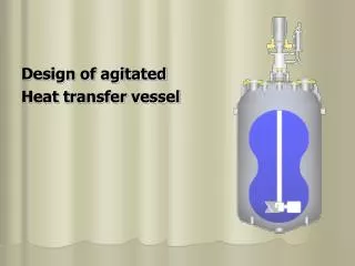
Heat Transfer in Agitated Vessel • Often it is necessary to cool or heat the contents of the vessel during agitation. • This is usually done by heat-transfer surfaces, which may be in the form of: 1) cooling or heating jackets in the wall of the vessel 2) coils of pipe immersed in the liquid.
Vessel with heating jacket • When heating, the fluid entering is often steam, which condenses inside the jacket and leaves at the bottom. • The vessel is equipped with an agitator and in most cases also with baffles (not shown). • Correlations for the heat-transfer coefficient from the agitated Newtonian liquid inside the vessel to the jacket walls of the vessel have the following form:
where: h is the heat-transfer coefficient for the agitated liquid to the inner wall in W/m2.K, Dt is the inside diameter of the tank in m, k is thermal conductivity in W/m.K, Da is diameter of agitator in m, N is rotational speed in revolutions per sec, ρ is fluid density in kg/m3, µ is liquid viscosity in Pa.s
EXAMPLE 4.13-1. Heat-Transfer Coefficient in Agitated Vessel with Jacket A jacketed 1.83-m-diameter agitated vessel with baffles is being used to heat a liquid which is at 300 K. The agitator is 0.61 m in diameter and is a flat-blade turbine rotating at 100 rpm. Hot water is in the heating jacket. The wall surface temperature is constant at 355.4 K. The liquid has the following bulk physical properties: ρ = 961 kg/m3, cp = 2500 J/kg.K, k = 0.173 W/m.K, and µ = 1.00 Pa.s at 300 K and 0.084 Pa.s at 355.4 K. Calculate the heat-transfer coefficient to the wall of the jacket.
Vessel with heating coil • Correlations for the heat-transfer coefficient to the outside surface of the coils in agitated vessel have the following form: a) for a paddle agitator b) for vertical baffle tube with a flat-blade turbine: Do is outside diameter of the coil tube (in m), nb is number of vertical baffle tubes and µf is the viscosity of the mean film temperature