Use Case Diagram in Detail
480 likes | 860 Vues
Use Case Diagram in Detail. CT1414 February 2012 By: Fatimah Alakeel Reviwed by: Asma Alzaid. use case. Use cases are technique for capturing functional requirements of a system. It describe the typical interaction between the users of the system and the system itself.

Use Case Diagram in Detail
E N D
Presentation Transcript
Use Case Diagram in Detail CT1414 February 2012 By: Fatimah Alakeel Reviwed by: AsmaAlzaid
use case Use cases are technique for capturing functional requirements of a system. It describe the typical interaction between the users of the system and the system itself. A scenario is a sequence of steps describing an interaction between a actors and a System . An actor is something with behavior, such as a person (identified by role), computer system, or organization; for example, a cashier.
Scenario Example (web based online store) The customer browses the catalog and adds desired items to the Shopping basket. When the customer wishes to pay, the customer describes the shipping and credit card information and confirms the sale . The System Checks the authorization and the credit card and confirms the sale both immediately and with a follow-up e-mail .
Use Case Start the use case by writing the main success scenario as a sequence number of step. Then take the other (alternative) scenario and write the as Extensions.
Main Success Scenario Example Buy a Product Goal Level : Sea Level Main Success Scenario : 1 . Customer browses catalog and selects items to buy 2 . Customer goes to check out 3. Customer fills in shipping information (address ; next-day or 3-day delivery) 4. System presents full pricing information, including shipping 5 . Customer fills in credit card information 6 . System authorizes purchase 7 . System confirms sale immediately B . System sends confirming e-mail to customer Extensions : 3a : Customer is regular customer .1 : System displays current shipping, pricing, and billing information .2 : Customer may accept or override these defaults, returns to MSS at step 6 6a : System fails to authorize credit purchase .1 : Customer may reenter credit card information or may cancel
Use Case Types and Formats Black-box use cases are the most common and recommended kind. They do not describe the internal workings of the system, its components, or design. The system is described as having responsibilities. Specify what the system must do (the functional requirements) without deciding how it will do it (the design).
Use Case Format Fully dressed - the most elaborate. All steps and variations are written in detail, and there are supporting sections, such as preconditions and success guarantees. Brief - terse one-paragraph summary, usually of the main success scenario. Casual - informal paragraph format. Multiple paragraphs that cover various scenarios.
Use Case Steps 1. Choose the system boundary. Is it just a software application, the hardware and application as a unit, that plus a person using it, or an entire organization? 2. Identify the primary actors. Those that have user goals fulfilled through using services of the system. 3. For each, identify their user goals. Raise them to the highest user goal level that satisfies the EBP guideline. 4. Define use cases that satisfy user goals; name them according to their goal. Usually, user goal-level use cases will be one-to-one with user goals, but there is at least one exception, as will be examined.
Actors Name • An actor is anything with behavior, including the system under discussion. • 3 kind of Actor: • Primary actor-> has user goals fulfilled through using services of the system under discussion. • Supporting actor-> provides a service to the system under discussion. • Offstage actor -> has an interest in the behavior of the use case, but is not primary or supporting
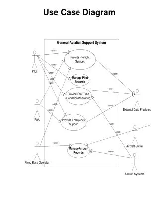
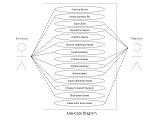
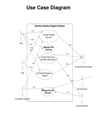
Using Use Case Diagrams • Use case diagrams are used to visualize, specify, construct, and document the (intended) behavior of the system, during requirements capture and analysis. • Provide a way for developers, domain experts and end-users to Communicate. • Use case diagrams contain use cases, actors, and their relationships.
= Use Case Use Case Do something • System function (process – automated or manual). Named by verb. • Each Actor must be linked to a use case, while some use cases may not be linked to actors.
Relationship • Relationship can be: • Between usecases • Between Actors • Between usecases and actors.
3.1 Relationships between Use Cases 1. Generalization - use cases that are specialized versions of other use cases. 2. Include - use cases that are included as parts of other use cases. Contain the functionality of another use case as part of their normal processing. 3. Extend - use cases that extend the behavior of other core use cases. Enable to factor variants.
parent child 1. Generalization • The child use case inherits the behavior and meaning of the parent use case. • The child may add to or override the behavior of its parent.
registration non-graduate registration graduate registration More about Generalization
Generalization Example • The actor Order Registry Clerk can instantiate the general use case Place Order. Place Order can also be specialized by the use cases Phone Order or Internet Order.
base included <<include>> 2. Include • The base use case explicitly incorporates the behavior of another use case at a location specified in the base. • The included use case never stands alone. It only occurs as a part of some larger base that includes it.
updating grades <<include>> verifying student id output generating <<include>> More about Include • Enables to avoid describing the same flow of events several times by putting the common behavior in a use case of its own. ניתוח מערכות מידע
Include relationship • Include relationship – a standard case linked to a mandatory use case. • Example: to Authorize Car Loan (standard use case), • a clerk must run Check Client’s Credit History (include use case). • The standard UC includesthe mandatory UC (use the verb • to figure direction arrow). • Standard use case can NOT execute without the include case tight coupling . • Note: Visio calls this “uses” relationship.
base extending <<extend>> 3. Extend • The base use case implicitly incorporates the behavior of another use case at certain points called extension points. • The base use case may stand alone, but under certain conditions its behavior may be extended by the behavior of another use case.
<<extend>> Exam-grade appeal Exam copy request More about Extend • Enables to model optional behavior or branching under conditions.
Extend relationship • Extend relationship – linking an optional use case • to a standard use case. • Example: Register Course (standard use case) may have • Register for Special Class (extend use case) – class for • non-standard students, in unusual time, with special • topics, requiring extra fees…). • The optional UC extends the standard UC • Standard use case can execute without the extend case • loose coupling.
student graduate student non-graduate student 3.2 Relationships between Actors • Generalization.
updating grades faculty 3.3 Relationships between Use Cases and Actors • Actors may be connected to use cases by associations, indicating that the actor and the use case communicate with one another using messages.
user place conference call place phone call receive phone call use scheduler <<extend>> cellular network receive additional call <<extend>> Cellular Telephone Example
Each use case may include all or part of the following: Title or Reference Name - meaningful name of the UC Author/Date - the author of the UC and its creation date Modification/Date - last modification to the UC and its date Purpose - specifies the goal to be achieved by the UC Overview - short description of the use cases processes Cross References - requirements references Actors - agents which initiate or participate in the UC Pre Conditions - must be true to allow the execution of the UC Post Conditions - will be set when the use use completes its execution normally Normal flow of events - regular flow of activities of the UC Alternative flow of events - other flow of activities of the UC Exceptional flow of events - unusual situations Implementation issues - possible foreseen problems in the implementation of the UC Use Case Description Each use case may include all or part of the following: • Title or Reference Name - meaningful name of the UC • Author/Date - the author and creation date • Modification/Date - last modification and its date • Purpose - specifies the goal to be achieved • Overview - short description of the processes • Cross References - requirements references • Actors - agents participating • Pre Conditions - must be true to allow execution • Post Conditions - will be set when completes normally • Normal flow of events - regular flow of activities • Alternative flow of events - other flow of activities • Exceptional flow of events - unusual situations • Implementation issues - foreseen implementation problems
Example- Money Withdraw • Use Case: Withdraw Money • Author: ZB • Date: 1-OCT-2004 • Purpose: To withdraw some cash from user’s bank account • Overview: The use case starts when the customer inserts his credit card into the system. The system requests the user PIN. The system validates the PIN. If the validation succeeded, the customer can choose the withdraw operation else alternative 1 – validation failure is executed. The customer enters the amount of cash to withdraw. The system checks the amount of cash in the user account, its credit limit. If the withdraw amount in the range between the current amount + credit limit the system dispense the cash and prints a withdraw receipt, else alternative 2 – amount exceeded is executed. • Cross References: R1.1, R1.2, R7
Example- Money Withdraw (cont.) • Actors: Customer • Pre Condition: • The ATM must be in a state ready to accept transactions • The ATM must have at least some cash on hand that it can dispense • The ATM must have enough paper to print a receipt for at least one transaction • Post Condition: • The current amount of cash in the user account is the amount before the withdraw minus the withdraw amount • A receipt was printed on the withdraw amount • The withdraw transaction was audit in the System log file
Example- Money Withdraw (cont.) • Typical Course of events:
Example- Money Withdraw (cont.) • Alternative flow of events: • Step 3: Customer authorization failed. Display an error message, cancel the transaction and eject the card. • Step 8: Customer has insufficient funds in its account. Display an error message, and go to step 6. • Step 8: Customer exceeds its legal amount. Display an error message, and go to step 6. • Exceptional flow of events: • Power failure in the process of the transaction before step 9, cancel the transaction and eject the card
Example- Money Withdraw (cont.) • One method to identify use cases is actor-based: - Identify the actors related to a system or organization. - For each actor, identify the processes they initiate or participate in. • A second method to identify use cases is event-based: - Identify the external events that a system must respond to. - Relate the events to actors and use cases. • The following questions may be used to help identify the use cases for a system: • What are tasks of each actor ? • Will any actor create, store, change, remove, or read information in the system ? • What use cases will create, store, change, remove, or read this information ? • Will any actor need to inform the system about sudden, external changes ? • Does any actor need to be informed about certain occurrences in the system ? • Can all functional requirements be performed by the use cases ?
Moving on • The “things” that “live” inside the system are responsible for carrying out the behavior the actors on the outside expect the system to provide. • To implement a use case, we create a society of classes that work together to carry out the behavior of the use case.
How to create use case diagram 1. List main system functions (use cases) in a column: • think of business events demanding system’s response • users’ goals/needs to be accomplished via the system • Create, Read, Update, Delete (CRUD) data tasks 2. Draw ovals around the function labels 3. Draw system boundary 4. Draw actors and connect them with use cases (if more intuitive, this can be done as step 2) 5. Specify include and extend relationships between use cases
Connection between Actor and Use Case Boundary of system Include relationship between Use Cases (one UC must call another; e.g., Login UC includes User Authentication UC) <<include>> <<extend>> Extend relationship between Use Cases (one UC calls Another under certain condition; think of if-then decision points) Elements of use case diagramSummary
name name Elements of use case diagramSummary Use case , starts with a verb Actor can be human or other system
Extra reading http://www.andrew.cmu.edu/course/90-754/umlucdfaq.html
References http://www.umanitoba.ca/faculties/management/faculty/btravica/9351/class8.ppt http://brd4.braude.ac.il/~zbarzilay/L04_UML1_UseCase[2].ppt http://www.ts.mah.se/RUP/RationalUnifiedProcess/process/modguide/md_ucgen.htm