Download
1 / 133
1.6k likes | 2.6k Vues
Radiation Detection Instrumentation Fundamentals. DETECTORS. General Principles of Radiation Detection.

E N D
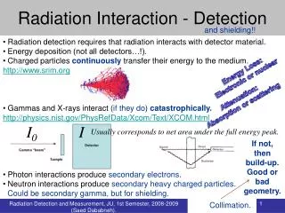
General Principles of Radiation Detection In order for the detector to respond at all, the radiation must undergo interaction through one interaction mechanisms. The interaction or stopping time is very small (typically a few nanoseconds in gases or a few picoseconds in solids). In most practical situations, these times are so short that the deposition of the radiation energy can be considered instantaneous
General Principles of Radiation Detection The net result of the radiation interaction in a wide category of detectors is the appearance of a given amount of electric charge within the detector active volume. Typically, collection of the charge is accomplished through the imposition of an electric field within the detector, which causes the positive and negative charges created by the radiation to flow in opposite directions. The time required to fully collect the charge varies greatly from one detector to another. For example, in ion chambers the collection time can be as long as a few milliseconds, whereas in semiconductor diode detectors the time is a few nanoseconds. These times reflect both the mobility of the charge carriers within the detector active volume and the average distance that must be traveled before arrival at the collection electrodes.
General Principles of Radiation Detection We can now introduce a fundamental distinction between three general modes of operation of radiation detectors. The three modes are called pulse mode, current mode, and mean square voltage mode. Pulse mode is easily the most commonly applied of these, but current mode also finds many applications. MSV mode is limited to some specialized applications that make use of its unique characteristics. Although the three modes are operationally distinct, they are interrelated through their common dependence on the sequence of current pulses that are the output of our simplified detector model
General Principles of Radiation Detection In pulse mode operation, the measurement instrumentation is designed to record each individual quantum of radiation that interacts in the detector. In most common applications, the time integral of each burst of current, or the total charge Q, is recorded since the energy deposited in the detector is directly related to Q. All detectors used to measure the energy of individual radiation quanta must be operated in pulse mode. Such applications are categorized as radiation spectroscopy and are subject of this lecture.
General Principles of Radiation Detection Characteristics of Pulse Mod Measurements • Puls Height Spectra • Energy resolution • Detection Efficiency • Dead Time
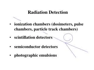
General Principles of Radiation Detection • Gas-Filled Detectors • Scintillation Detectors • Solid State Detectors
Gas-Filled Detectors - Components Variable voltage source Gas-filled counting chamber Two coaxial electrodes well insulated from each other
Gas-Filled Detectors Basic principle Electron-ions pairs • produced by radiation in fill gas • move under influence of electric field • produce measurable current on electrodes, or • transformed into pulse
Gas- Filled Detectors - one example A wall fill gas Output Anode (+) End window Or wall Cathode (-) or R
Indirect Ionization Process wall e - e - e - e - e - e - e - e - Incident gamma photon
Direct Ionization Process wall beta (β-) e - e - e - e - e - e - e - e - Incident charged particle
Competing Processes - recombination + + Output e - e - R
Operating Regions of Gas-Filled Detectors Proportional Region Pulse Height Ionization Region Continuous Discharge Region Recombination Region Limited Proportional Region Geiger-Mueller Region Voltage
Ionization ChambersVoltage versus Ions Collected Recom- bination region Ionization region Number of Ion Pairs collected Saturation Voltage 100 % of initial ions are collected Voltage
Saturation Current The point at which 100% of ions begin to be collected All ion chambers operate at a voltage that produces a saturation current The region over which the saturation current is produced is called the ionization region It levels the voltage range because all charges are already collected and rate of formation is constant
Observed Output: Pulse Height • Ions collected • Number of ionizations relate to specific ionization value of radiation • Gas filled detectors operate in either • current mode • Output is an average value resulting from detection of many values • pulse mode • One pulse per particle
Pulse Height Variation Alpha Particles Pulse Height Beta Particles Gamma Photons Detector Voltage
Ionization Region Recap • Pulse size depends on number of ions produced in detector. • No multiplication of ions due to secondary ionization (gas amplification is unity) • Voltage produced (V) = Q/C • Where • Q is total charge collected • C is capacitance of the ion chanber
Ionization Chambers, continued • Chamber’s construction determines is operating characteristics • Physical size, geometry, and materials define its ability to maintain a charge • Operates at a specific voltage • When operating, the charge collected due to ionizing events is Q = CΔV
Ionization Chambers, continued • The number of ions (N) collected can be obtained once the charge is determined: N = Q / k • Where k is a conversion factor • (1.6 x 10⁻¹⁹C/e)
Current vs. Voltage for Fill Gases in a Cylindrical Ion Chamber Air at high pressure 100 Helium at high pressure Relative Current (%) 10 Air at low pressure 1.0 Helium at low pressure 0.1 Applied Voltage (volts)
Proportional Counters Operates at higher voltage than ionization chamber Initial electrons produced by ionization are accelerated with enough speed to cause additional ionizations cause additional free electrons produces more electrons than initial event Process is termed: gas amplification
Pulse-Height Versus Voltage Ionization Region Proportional Region Recombination Region Pulse Height Voltage
Selection of the Operating Voltage • For charged radiations such as alpha or beta particles, a signal pulse will be produced for every particle that deposits a significant amount of energy in the fill gas. • The proportional counters are seldom operated in a mode that is sensitive to single avalanches in order to prevent nonlinerities for larger pulses due to space charge efects.
Fill gas • selected to enhance gas multiplication • no appreciable electron attachment • most common is P-10 (90% Argon and 10% methane)
Distinguishing Alpha & Beta • Proportional counters • can distinguish between different radiation types • specifically alpha and beta-gamma • Differential detection capability • due to size of pulses produced by initial ionizing events • requires voltage setting in range of 900 to 1,300 volts • alpha pulses above discriminator • beta/gamma pulses too small
Alpha Counting • For alpha particle sources, proportional counters can record easily each particle that enters the active volume with virtually 100% efficiency. • Absolute measurements of alpha source activity are therefore relatively straightforward and involve evaluation of the thje effective solid angle subtended by the counter active volume. • Windowless
Beta Counting • For beta particles of typical energies, the particle range greatly exceeds the chamber dimensions. • The numbers of ion pairs formed in the gas is then proportional to only that small fraction of the particcle energy lost in the gas before reaching the opposite wall
Gas-Flow Proportional Counter Fill gas outlet Fill gas inlet anode (window- optional) Detector O-ring sample Sample planchet
Variants of the Proportional Counter DesignPosition-Sensitive Proportional Counters
Multiwire Proportional Counters • In some situations, it is advantageous to provide more than one anode wire within a proportional counter. • Detectors with very large surface area can be constructed by placing a grid of anode wires between two large flat planes that serves as cathodes on either side of the counter
Microstrip Gas Chamber • On insulating substrate , metallic electrodes are formed by etching techniques. • The anode structures are kept quite narrow (typically 10 microns) so that the same type of concentration of the electric field that occurs around the wire is realized near the surface of the anode strip. • Thus avalanches will be formed as electrons are drawn in to the anode strip surface
Geiger Mueller Detectors • Operate at voltages above proportional detectors • Each primary ionization • produces a complete avalanche of ions throughout the detector volume • called a Townsend Avalanche • continues until maximum number of ion pairs are produced • avalanche may be propagated by photoelectrons • quenching is used to prevent process
Geiger Mueller Detectors A typical pulse from Geiger tube represents a large amount of collected charge, about 1010 ion pairs being formed in the discharge. No proportional relationship between energy of incident radiation and number of ionizations detected A level pulse height occurs throughout the entire voltage range
Geiger Mueller DetectorsFill Gases • Noble gases with helium and argon the most popular choices. • Even trace amounts of gases that forms negative ions (such as oxygen) must be avoided • Operate at atmospheric pressure or tenths of an atmospheric presurre. • Operating voltages up to 2000 V.
Geiger Mueller DetectorsQuenching • The problem of multiple pulsing is severe in Geiger tubes. • Internal quenching is accomplished by adding a second component called the quenching gas to the primary fill gas, in proportion of 5-10%. • Large organic molecules like ethyl alcohol and ethyl formade prevent the reemission of free electrons from the cathod.
Advantages/Disadvantages of Gas-Filled Detectors Ion Chamber: simple, accurate, wide range, sensitivity is function of chamber size, no dead time Proportional Counter: discriminate hi/lo Linear Energy Transfer, higher sensitivity than ion chamber GM Tube: cheap, little/no amplification, thin window for low energy; limited life
Issues with Gas Filled Detectors: Dead Time • Minimum time at which detector recovers enough to start another avalanche (pulse) • The dead time may be set by: • limiting processes in the detector, or • associated electronics • “Dead time losses” • can become severe in high counting rates • corrections must be made to measurements
Issues with Gas Filled Detectors: Recovery Time Time interval between dead time and full recovery Recovery Time = Resolving time- dead time
Issues with Gas Filled Detectors: Resolving Time Minimum time interval that must elapse after detection of an ionizing particle before a second particle can be detected.
Relationship among dead time, recovery time, and resolving time 0 100 200 300 400 500 Pulse Height Dead Time Recovery time Resolving time Time, microseconds