Working group on rf and feedback
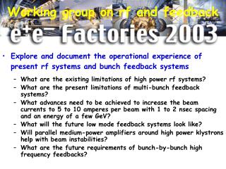
Working group on rf and feedback. Explore and document the operational experience of present rf systems and bunch feedback systems What are the existing limitations of high power rf systems? What are the present limitations of multi-bunch feedback systems?

Working group on rf and feedback
E N D
Presentation Transcript
Working group on rf and feedback • Explore and document the operational experience of present rf systems and bunch feedback systems • What are the existing limitations of high power rf systems? • What are the present limitations of multi-bunch feedback systems? • What advances need to be achieved to increase the beam currents to 5 to 10 amperes per beam with 1 to 2 nsec spacing and an energy of a few GeV? • What will the future low mode feedback systems look like? • Will parallel medium-power amplifiers around high power klystrons help with beam instabilities? • What are the future requirements of bunch-by-bunch high frequency feedbacks?
Monday - rf and feedback systems • Tuesday - collective effects • Wednesday • Joint session’s • KEKB-Linac Upgrade Plan Using C-Band System for SuperKEKB (Fukuda) • PEP-II low-level rf fault file analysis (Teytelman) • Strong RF Focusing: a possible approach to get short bunches at the IP (Gallo) • Future very high luminosity options for PEP-II (Seeman) • Analytical Treatment of NonLinear Beam Dynamics in a Storage Ring (Gao) • Associates: Dmitry Teytelman and Peter McIntosh • Chair: John Corlett + Ops group + BB group
RF and feedback presentations • ARES Upgrade for Super-KEKB – Tetsuo Abe • Bunch Shortening using Superconducting Harmonic Cavities – John Byrd • The DAFNE 3rd Harmonic Cavity – Alessandro Gallo • Update on the Performance of Superconducting Cavities in KEKB – Takaaki Furuya • Analysis of rf and feedback limitations in PEP-II – Dimitri Teytelman • The Linac Upgrade Plan Using A C-band System for SUPERKEKB –S. Fukuda • PEP-II low-level rf fault file analysis– Dimitri Teytelman
ARES Upgrade for Super-KEKB – Tetsuo Abe • ARES cavity system uses three normal-conducting cavities coupled together • Accelerating cavity, coupling cavity, storage cavity • P/2 mode • System has large stored energy • Reduced detuning • Fundamental does not strongly drive coupled-bunch modes under design conditions
Tetsuo Abe • For Super KEK-B operations up to 9.4 A • Increase ratio of stored energy to accelerating mode energy • From Us/Ua = 9 to Us/Ua = 15 • Change cavity coupling • New accelerating cavities • Prototype in 2004
Tetsuo Abe • Need rf feedback system to control m=-1, -2 modes • Under development • Need broadband longitudinal feedback for fundamental 0 and p modes, and HOM-driven modes • 80 kW dissipated per cavity • Need more absorbers and water cooling • Developing multipactor-free coaxial rf power coupler
Passive harmonic cavities for bunch shortening – John Byrd • Use reactive longitudinal focusing from beam-induced voltage in a cavity • Use SC cavity so that • Low beam losses • Higher voltages • Use at RF harmonic to get larger dV/dt Beam induced voltage V=jI(R/Q)fr/df Voltage completely reactive (i.e. 90 phase shift w.r.t beam)
John Byrd • Using 2 SC cells (R/Q=87 Ohms,Q=2e8), proper tuning can shorten the bunches in PEP-II by a factor of 2.5 • Existence proofs for cavities at BESSY and ELETTRA • Need to assess effects for large rings • low-mode coupled-bunch modes • differential tune shift is important
The DAFNE 3rd harmonic cavity– Alessandro Gallo • Passively powered harmonic cavity to lengthen the bunches. • Touschek lifetime increase, due also to improvements of the dynamic aperture and RF acceptance, is 80%; • Additional positive effects • larger Landau damping • larger natural bunch length • Low R/Q - coherent synchrotron frequenciesshift are under control
Alessandro Gallo • The “parking option”, as a reliable back-up procedure • Two cavities have been designed, built and tested on bench • Suppression of the HOMs with KEK-B SBP ferrite damper • Measurements are in substantial agreement with MAFIA and HFSS simulations • Wide tuning range • 5 revolution harmonics around the RF 3rd harmonic
Alessandro Gallo A. Gallo: The DAFNE 3rd Harmonic Cavity If the harmonic voltage is phased to reduce the total RF slope, the bunch natural length increases. The further lengthening produced by the ring wakes can be estimated by a multiparticle tracking simulation Working point of the main and harmonic RF systems
Alessandro Gallo • Gap in the bunch filling pattern produces a large spread of the synchronous phases. Different bunches will collide at slightly different IPs and the synchronization of the bunch-by-bunch feedback systems may be affected • Different bunch distribution along the train • Touschek lifetime gain is not uniform over the train
Round Aluminium Cell • R/Q 25 • Wide Tunability (-1.5 frev 3.5 frev) • KEK-B Ferrite Damper • No direct Ferrite exposure to the Beam Alessandro Gallo
Update on the Performance of Superconducting Cavities in KEKB– Takaai Furuya * RF of HER is a combination of SC & NC * Crab cavities is just under R&D phase SC cavities in NIKKO straight section.
Takaai Furuya SC Cavities in KEKB Cavity *Nb single-cell *Frequency: 508 MHz *Gap length: 0.243 m *R/Q : 93 Ohm *Total length: 3.7 m
Takaai Furuya SC cavities are slightly conditioned every two weeks for about two hours
Takaai Furuya Unloaded Q
Takaai Furuya • Super KEK-B • Increased beam power • Modify coaxial power feed to avoid multipacting • Modify ferrite dampers to accommodate 50 kW beam induced power
Takaai Furuya Monitoring beam-abort • Coupling and reaction between RF cavities and stored beams is quite strong in ampere class accelerators • Difficult to identify the real reason of beam loss or RF-trip events • 24ch-data logger • 650 ms history with 5 ms resolution • RF signals • Radiation monitor at movable masks • Beam synchronous phase
Limitations and upgrade options for PEP-II • PEP-II low-level rf fault file analysis– Dmitry Teytelman • PEP- II designed to operate above instability threshold in all 3 planes: horizontal, vertical and longitudinal • Beam is kept stable via a combination of three techniques • HOM damping in RF cavities – longitudinal and transverse • Bunch- by- bunch feedback systems - longitudinal and transverse • Active impedance reduction for the fundamental mode of the RF cavities - longitudinal
Dmitry Teytelman • PEP- II beam loading • RF cavities must be detuned beyond first revolution harmonic • Worst- case growth time for mode -1 is 33 ms • 185 m s synchrotron period!
Dmitry Teytelman • Direct proportional feedback loop around the cavity • Reduces the effective impedance seen by the beam • To reduce the growth rates further we add the comb filter • Narrow gain peaks at synchrotron sidebands • Growth rates shown for a linear transfer function model • Reduction by two orders of magnitude, from 30 to 0.35 ms -1
Dmitry Teytelman Feedback systems currently running near maximum usable gain to control fundamental- driven modes
Dmitry Teytelman • Klystron saturation • Linear model is not applicable • HER at 1 A the growth rates rise from linear prediction • 0.12 to actual 1- 1.8 ms-1
Dmitry Teytelman • Techniques to combat increased growth rates • Reduce klystron saturation by installing tubes with full- power collectors and improved water cooling • Dedicated “woofer” link from feedback system to rf stations • Single- sideband comb filters • Use a separate (linear) feedback amplifier in parallel with the klystron • Energy storage cavities • Superconducting RF
Dmitry Teytelman • Fault analysis • RF processing module • Circular buffer records I&Q components • ADC samples at 10 MHz • Recording stops on beam abort signal
Dmitry Teytelman • Nice steady- state running with periodic gap transient. After the last turn the beam does not arrive in the cavity after the gap - cavity charges up to high voltage • Synchronization to the gap indicates that the abort kicker fired after the last recorded turn (around 5.212 ms). • When the beam disappears the cavity becomes mismatched to the generator and we get large reflected power. • However, the primary event that causes the reflected power trip is the abort kicker firing.
Dmitry Teytelman Forward power of all HER stations is shown Around 4 ms power contribution of stations in Region 8 goes down and of those in Region 12 – up This event is due to a differential phase shift of the RF reference between Regions 8 and 12.
Dmitry Teytelman RF- related events are defined as beam aborts described in the operations log as being caused by ring RF system or longitudinal instabilities. Generate summary from daily analysis of all RF- related beam aborts. Analysis is based on fault files saved by RF stations during a beam abort event and is very time- consuming.
The Linac Upgrade Plan Using A C-band System for SUPERKEKB –Shigeki Fukuda
Shigeki Fukuda Requirements for SuperKEKB (1) KEKBSuperKEKB Beam Energy (e-) 8.0 GeV -----> 3.5 GeV(8.0 GeV) (e+) 3.5 GeV -----> 8.0 GeV !! (3.5 eV) NEED Energy upgrade for e+ !-> C-band accelerator units (2) June 2002 designKEKBSuperKEKB Stored current (e-) 0.95 A --> 1.1 A ---> 9.4 A !!(4.1 A) (e+) 1.5 A --> 2.6 A ---> 4.1 A !!(9.4 A) NEED Intensity upgrade for e-/e+ ! -> flux concentrator, more bunch charge, 2-bunch operation (3) Mode-switching -> Continuous & Simultaneous e+/e- Injection -> optimization of layout, 2-bunch operation Pink: unswitched case
Scheme-1 (Energy switched) Shigeki Fukuda e+ energy is boosted by the C-band units. 2-bunches from the gun are used for simultaneous injection of e- (LER) and e+ (HER) in a same RF pulse. Energy gain S-band: 1.28 GeV/sector -> C-band: 2.56 GeV/sector (New constructions) e+ focusing flux concentrator Damping Ring @ e+ 1.0 GeV Sector-3, 4, 5 : -> C-band units e– BT-line @ e– 3.5 GeV
Scheme-2 (Energy unswitched) Shigeki Fukuda e+/e- modes are switched. (quasi-)simultaneous injection is difficult poor e+ intensity (New constructions) e+ focusing flux concentrator Damping Ring @ e+ 1.0 GeV
Shigeki Fukuda Scheme 1+2 (Energy (un)switched) Energy gain S-band: 1.28 GeV/sector -> C-band: 2.56 GeV/sector Even for the unswitched case, the C-band units enables to separate the e+ and e- beam lines, the simultaneous injection or pulse-to-pulse mode switching. (New constructions) e+ focusing flux concentrator Damping Ring @ e+ 1.0 GeV Sector-3, 4, 5 : -> C-band units e– BT-line @ e– 3.5 GeV
Shigeki Fukuda Summary of C-band linac • High power rf processing of 1m C-band accelerator guide for Super KEKB was successfully performed and power corresponding to 42 MV/m was achieved • Acoustic sensors to investigate possible arcing • Processed accelerator was installed in the beam line of KEKB linac and being re-processed. The beam acceleration of 40MV/m was successfully achieved in October 2003
Collective effects presentations • Potential-Well Distortion in RF Barriers - King Ng • Multi-bunch Longitudinal Instability due to the Electron Cloud - Sasha Novokhatski • Recent Observations of Collective Effects at KEKB - Hitoshi Fukuma • Collective Effects for the PEP-II Upgrade - Samuel Heifets
Barrier rf system • Beam spreads out with lower space-charge force • Can merge two batches together easily • Can compress by moving a barrier slowly • Can move batch from one location to another • If baseline is not zero,rf potential will be head-tail asymmetric • Head-tail asymmetry King Ng
King Ng • Can correct by adjusting rf system • Properly adjusted rf system introduces opposite asymmetry • Small voltage (~ 10V in 2 kV rf system) restores linearity
King Ng • Remaining problems • The voltage compensation is smaller than actually used • The predicted slant is not linear • Elliptical-like distribution does not fit measured energy spread
Multi-bunch Longitudinal Instability due to the Electron Cloud - Sasha Novokhatski
Sasha Novokhatski Electric force lines from electron cloud Positron bunch Positron bunch “head” is accelerated “tail” is decelerated
Sasha Novokhatski Multipacting AT 38 G
Sasha Novokhatski Longitudinal electric field If electron cloud happens in all straight sections, the energy variation in a positron bunch can be of order of 74 kV, which is equivalent to 185 kV of RF voltage of 476 MHz.
Sasha Novokhatski Instability along bunch train
Sasha Novokhatski • Longitudinal electric field produces an oscillating force on the cloud electrons • Adds energy variation inside the positron bunches • head of the positron bunch is accelerated and the tail is decelerated • This action of the longitudinal field is similar to the action of RF fields in a cavity and has the same sign • Bunches will have different lengths throughout the train • Electron cloud space-charge field acts as a resonance force for the longitudinal beam motion • Emittance growth • Longitudinal multi-bunch instability
Recent Observations of Collective Effects at KEKB - Hitoshi Fukuma • 3 and 4 bucket spacing : the threshold increases when the field strength increases 2 spacing : the threshold saturates • Assuming a present solenoid system, stronger field will be helpful in raising the threshold if bunch spacing is larger than/equal to 3 buckets.
Tune shift by e-cloud Hitoshi Fukuma 4 trains, 200 bunches/train, 4 bucket spacing, bunch current 0.58mA 4 trains, 200 bunches/train, 2/3/4 bucket spacing, bunch current 0.5mA, with 100% solenoid
Hitoshi Fukuma Blowup vs. location of e-cloud 4 trains, 200 bunches/train, 3 bucket spacing Tsukuba straight section off West arc off all solenoid on Fuji straight section off 1. The solenoids in the straight sections are effective on the blowup, even in Fuji straight section where no wiggler magnets are installed. 2. Effect of solenoids on the threshold current of the blowup 1/4 arc > Fuji straight > Tsukuba straight