1 / 6

Kapton Foil Specifications and Clearance Areas for IPT Connections

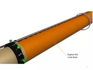
This document outlines the specifications for Kapton foil used in IPT connections, detailing the thickness of 1 mil and highlighting the various clearance areas. It specifies the limited clearance area of 1.115 mm and the normal clearance area of 1.27 mm. Additionally, it describes the configurations of Kapton foil layers with options for 3, 4, 5, and 7 plies. These specifications ensure optimal performance and reliability in applications requiring precise connections and insulation.

trella
Télécharger la présentation

Kapton Foil Specifications and Clearance Areas for IPT Connections

An Image/Link below is provided (as is) to download presentation Download Policy: Content on the Website is provided to you AS IS for your information and personal use and may not be sold / licensed / shared on other websites without getting consent from its author. Content is provided to you AS IS for your information and personal use only. Download presentation by click this link. While downloading, if for some reason you are not able to download a presentation, the publisher may have deleted the file from their server. During download, if you can't get a presentation, the file might be deleted by the publisher.

E N D

Presentation Transcript


  1. Kapton foil 1 mil thick

  2. IPT Connection area

  3. Kapton foil area Limited clearance area (1.115 mm) Normal clearance area (1.27 mm)

  4. RING IP SIDE KAPTON 3 plies 7 plies 5 plies 4 plies 4 plies

  5. RING IP SIDE KAPTON 3 plies 7 plies 5 plies 4 plies 4 plies

More Related