Download
1 / 20
310 likes | 1.3k Vues
Overview of CANDU Reactor Technology and the CANDU 9 Simulator. Matthias Krause Nuclear Power Technology Development Section (NPTDS) May 2014. Why Nuclear, and How?. Quality of Life needs sustainable, affordable energy/electricity.

E N D
Overview of CANDU Reactor Technology and the CANDU 9 Simulator Matthias Krause Nuclear Power Technology Development Section (NPTDS) May 2014
Why Nuclear, and How? • Quality of Life needs sustainable, affordable energy/electricity. • “Nuclear power is the only existing option for large scale power production that transcends the limitations of non-renewable alternatives (such as coal, oil and gas) and renewable alternatives (wind, solar and biomass).” • Basic functional requirements for a Nuclear Reactor: • Fuel such as U-235 • A moderator to thermalize fast neutrons • Coolant to remove the heat • Control systems to control the number of neutrons/fissions • Shielding to protect equipment and people • Safe engineered systems that work together
Stylized Nuclear Power Reactor Simulators model most systems and sub-systems in a stylized, but “tuned” manner. Safety Analysis codes model individual systems with more physical detail and less tuning.
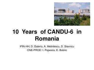
Heavy Water Reactors based on the CANDU design in operation, under construction, or under refurbishment - located on four continents Romania Cernavoda 2 units Quebec, Canada Gentilly 2 1 unit Ontario, Canada Darlington 4 units Pickering 6 units Bruce 8 units Republic of Korea Wolsong 4 units China Qinshan 2 units India 13 units, 5 units under construction, 2 in pre-project phase New Brunswick, Canada Point Lepreau 1 unit Argentina Embalse 1 unit Pakistan KANUPP 1 unit Point Lepreau, Canada Qinshan, China Pickering, Canada
Calandria tube Pressure tube Fuel Fuel channels Calandria Fueling machine The CANDU Reactor Core - Components
CANDU Fuelling • Online refuelling at a rate of ~24 bundles or ~0.5% per FPD • “Equilibrium core” with a mix of fresh and “burned-up” fuel • Slight power shape changes • Refuelling is the full-time job of the reactor station physicist • Refuelling simulators are available, but refuelling is NOT part of the “normal” plant simulators
The CANDU Reactor Core – Reactivity Control Two capable, fast, independent low-pressure SDS’s SDS-1: 28 Cd Rods SDS-2: 6 Gdpoison injection nozzles Three RRS or reactivity control devices: LZC – normally ~50% Adjusters – normally fully IN Absorbers – normally fully OUT (SDR withdrawal only) Diverse neutronic detectors Huge heavy and light water inventories act a passive heat sinks during prolonged accidents
REACTIVITY WORTHS OF CANDU-6 REACTIVITY DEVICES Function Device Total Reactivity Worth (mk) Maximum Reactivity Rate (mk/s) Control 14 Liquid Zone Controllers 7 0.14 Control 21 Adjusters 15 0.10 Control 4 Mechanical Control Absorbers 10 0.075(driving) - 3.5 (dropping) Control Moderator Poison — -0.01 (extracting) Safety 28 Shutoff Units -80 -50 Safety 6 Poison-Injection Nozzles >-300 -50
New Generation PHWRs • Enhanced CANDU 6 (EC6) • 740 MWe • Evolution of CANDU 6 (NU, heavy water coolant and moderator) • Improvements based on Qinshan feedback and current customer requirements • Enhanced safety, improved containment • ACR-1000 • ~1150 MWe, Generation III+ technology • Combines experience of CANDU 6 with new concepts (LEU, light water coolant, heavy water moderator) • Enhanced safety, economics, operability
The Simulator 1. Plant Overview 2. Shutdown Rods 3. Reactivity Control 4. PHT Main Circuit 5. PHT Feed & Bleed 6. PHT Inventory Control 7. PHT Pressure Control 8. Bleed Condenser Control 9. SG Feed Pumps 10. SG Level Control 11. SG Level Trends 12. SG Level Man. Control 13. Extraction Steam 14. Turbine Generator 15. RRS / DPR 16. UPR 17. Trends
Plant Overview Panel • Alarm Panel (top - common) • A ‘line diagram’ of the main plant systems and parameters • Moderator not modelled • Core with PK model for fission and decay • PHTS avg parameters • SG and steam header • Valves (red = OPEN) • Simplified feedwatersyst • 6 realtime trend displays • Control (bottom – common) • Panel/Manual Trips • Main Reactor Parameters • Simulator Run Control Overall Unit Control: Normal (turbine leads reactor) Alternate (reactor leads turbine)
Reactivity Control Panels Three RRS or reactivity control devices: LZC – normally ~50% Adjusters – n. fully IN Absorbers – n. fully OUT (SDR withdrawal only) Diagram shows “Operating Point”, which defines automatic actions of AD and AB rods All devices can be under AUTO or MAN control (different panel) the movement of the AD and AB rods is designed to return the operating point (the intersection of power error and average zone level) to the central region
Primary-Side Panels • No control, parameter display only - Control of PHT sub-systems on detailed panels: • Feed & Bleed • Inventory • Pressure • Pressurizer Bleed Condenser The 480 channels are represented by four channels, two per loop with opposite flow directions, in the “figure of eight” configuration
Secondary-Side Panels • No control, parameter display only - Control of secondary-side systems on detailed panels: • Feed pumps • Man. Level control • Extraction steam Detailed display of SG alarm, control, and trip points on separate panel
Custom Parameters Panel • Plot 8 out of 65 available parameters to view parameters from different systems on one display. • Control of x-axis (time) • Automatic y-axis scale
Two Simulator Exercises • 2.3 Reactor and RRS Response to Power Manoeuvre • 6.6 Main Steam Header Break
Limitations of CANDU Simulator • Only equilibrium core • No refuelling transients • No fresh/depleted fuel operation (initial reactor startup) • No moderator and containment systems • no moderator/containment trips (e.g. for LOCAs) • No large LOCA or ECC system, no LOC4P(SBO) • no simulation of “power pulse” • Very limited DBA and no SA simulation • Some of the above are included in ACR simulator
ACR Simulator Example • LOCA in Reactor Inlet Header RIH#1 • Plant Overview – show main features • RCS/Trip Parameters – watch for ROH-LP trip • RRS – observe SD actions and Flux Map • ECC/Passive Cooling – observe ECC actions