Embedded System Requirements, Specification and Modelling
Embedded System Requirements, Specification and Modelling. K. Tatas Sources: Hermann Kopetz, “Real-Time Systems: Design Principles for Distributed Embedded Applications”, Springer, 2011

Embedded System Requirements, Specification and Modelling
E N D
Presentation Transcript
Embedded System Requirements, Specification and Modelling K. Tatas Sources: Hermann Kopetz, “Real-Time Systems: Design Principles for Distributed Embedded Applications”, Springer, 2011 Wayne Wolf, “High-Performance Embedded Computing: Architectures, Applications, and Methodologies”, Morgan Kaufmann, 2006 Wayne Wolf, “Computers as components: Principles of embedded computing design”, Morgan Kaufmann Publishers, 2000
Introduction • Distributed Embedded System Models • Design/Abstraction Levels • Embedded System Design Flow • Embedded System Requirements • Embedded System Specifications • Object-oriented Design • Unified Modeling Language (UML) • SystemC and TLM
Classification of Embedded Systems • Real-time • Hard deadline • Failsafe • Fail-operational • Soft and firm deadline • Non-Real-time
Fail-Safe hard-deadline RT systems • If a safe state can be identified and quickly reached upon the occurrence of a failure, then we call the system fail-safe. • Failsafeness is a characteristic of the controlled object, not the computer system. • In case a failure is detected in a railway signaling system, it is possible to set all signals to red and thus stop all the trains in order to bring the system to a safe state. • In failsafe applications the computer system must have a high error-detection coverage. • Often a watchdog, is required to monitor the operation of the computer system and put it in safe state.
Fail-Operational hard-deadline RT systems • In fail-operational applications, threre is no safe state • a flight control system aboard an airplane. • The computer system must remain operational and provide a minimal level of service even in the case of a failure to avoid a catastrophe
Guaranteed response systems • a design that operates correctly even in the case of a peak load and fault scenario is a system with a guaranteed response. • The probability of failure of a perfect system with guaranteed response is reduced to the probability that the assumptions about the peak load and the number and types of faults do not hold in reality. • This probability is called assumption coverage [Pow95]. • Guaranteed response systems require careful planning and extensive analysis during the design phase.
Best-effort systems • If an analytic response guarantee cannot be given, we speak of a best-effort design. • Best-effort systems do not require a rigorous specification of the load- and fault-hypothesis. • The design proceeds according to best effort • the sufficiency of the design is established during the test and integration phases. • It is difficult to establish that a best-effort design operates correctly in a rare-event scenario. • Many non safety-critical real-time systems are designed as best-effort systems.
Resource adequacy • Guaranteed response systems are based on the principle of resource adequacy, i.e., there are enough computing resources available to handle the specified peak load and the fault scenario. • Many non safety-critical real-time system designs are based on the principle of resource inadequacy. • If providing sufficient resources to handle every possible situation is not economically viable, then a dynamic resource allocation strategy based on resource sharing and probabilistic arguments about the expected load and fault scenarios is used • Hard realtime systems must be designed according to the guaranteed response paradigm that requires the availability of adequate resources.
Distributed RT system model • From the POV of an outside observer, a real-time (RT) system can be decomposed into three communicating subsystems: • a controlled object (the physical subsystem, the behavior of which is governed by the laws of physics), • a “distributed” computer subsystem (the cyber system, the behavior of which is governed by the programs that are executed on digital computers) • a human user or operator • The distributed computer system consists of computational nodes that interact by the exchange of messages. • A computational node can host one or more computational components.
Local clocks • Every node of a distributed system has a local oscillator that ticks with a frequency determined by the physical parameters of the oscillator. • Typical maximum drift rates r of physical clocks are in the range from 10^-2 to 10^-7 us/s, or lower, depending on the quality (and price) of the resonator • Local real-time clocks in each node have a a varying drift rate
Clock synchronization • The global ticks of all correct nodes must occur within a specified precision P • clock synchronization should not depend on the correctness of a single clock • A subset of the local oscillator’s microticks is interpreted as the global time ticks at the node. • These global time ticks increment the local node’s global time counter.
Event-Triggered Control Versus Time-Triggered Control • Event-triggered control is based on processor interrupts from external devices • Time-triggered control is based on polling external devices at regular intervals
Example of event-triggered control int led = 77;volatile int state = LOW;void setup(){ pinMode(led, OUTPUT); attachInterrupt(1, blink, RISING);}void loop(){ digitalWrite(led, state);}void blink(){ state = !state;}
Example of time-triggered control int led = 77; int sw = 2; volatile int state = LOW;void setup(){ pinMode(led, OUTPUT); digitalWrite(led, state); }void loop(){ if (digitalRead(sw)==HIGH) state = !state; delay(1000); }
Question • Which time of triggering would be more efficient for an elevator control system? • What do you think are the advantages/disadvantages of each?
Power consumption • The concept of energy refers to a scalar quantity that describes the capability of work that can be performed by a system • The intensity of the work, that is the energy used up per unit of time, is called power. Energy is thus the integral of power over time. • There exist different forms of energy, such as potential energy, kinetic energy, thermal energy (heat), electrical energy, chemical energy, and radiation energy • The first law of thermodynamics, relating to the conservation of energy, states that in a closed system, the total sum of all forms of energy is constant. • The second law of thermodynamics states that thermal energy can only be partially transformed to other forms of energy.
Energy Estimation • The energy that is needed by a computing device to execute a program can be • expressed as the sum of the following four terms:
Computation energy • The computation power main component is dynamic power • And the energy is equal to • Ecomp=Ceff*V^2*f*N • Where N is the number of executed instructions
Memory energy • Memory power consumption is higher than computation power consumption • Depends on the type of memory being accessed • Scratchpad memory that is within an IP-core. • Shared on-chip memory accessed via the NoC. • Off-chip memory, e.g., a large DRAM, that is accessed via the NoC and a memory gateway to the memory chip. • gross estimation: a memory access for a 32 bytes block of on-chip memory requires 1000 nJ and access to the off-chip memory requires about twenty times as much, i.e., 20 mJ.
Communication Energy • The energy needed by a sender Etx to transport a bit string of k bytes can be approximated by: • while the energy needed by the receiver Erx can be approximated by
Energy for wired communication • Etr = d*Ceffunit*V^2 • Where d is the distance • Ceffunit approx 1 pF/cm in on-chip interconnect • V is the supply voltage
Energy for wireless communication • For wireless communication, the transmit energy per bit can be approximated by • Etr = b*d^2
Energy Sources • There are three energy sources: • energy from the power grid, • energy from a battery • energy harvested from the environment
Batteries • An erratic power request pattern from the computer system could reduce the nominal battery power by as much as 50% • In this case an ultra capacitor is needed to spikes
Example • Evaluate the feasibility of an 2AA battery-powered embedded system with an operating frequency of 500 MHz that: • Is idle 90% of the time • There is no computation power when idle • When not idle it executes 1 instruction per clock cycle • All instructions come from on-chip memory and they are four bytes long • The effective capacitance is 1nF • It sends 1KB/h of data wirelessly to a distance of 100 m • b=100 pJ/(bit/m^2).
Embedded System Design Flow • Traditional Embedded System Design Flow
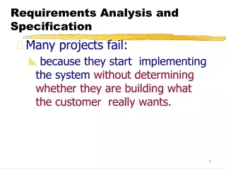
Problems with Traditional Design Flow • Gaps (manual translation) between Algorithm and Architecture level, and between Architecture level and RTL • Document specifications can be misinterpreted by design teams • Raising the level of abstraction that allows automatic translation to lower levels is required as system complexity increases • Software has to wait for hardware before being debugged
Embedded System Requirements • Essentially turning a concept into a product • Asking potential customers, understanding their needs • determining the best feature and price point • Sales and marketing usually responsible • R&D engineers should contribute
Embedded System Requirements • Functional: describe each function of the system • Input: • Output: • Processing: • Non-functional: system properties not related to its function • Cost • Time-to-market • Reliability • Portability • Maintainability • Security
Requirements should be • Concise: • Brief yet complete and unambiguous • Structured: • Requirements should be numbered • Black-box view: • Not concerned with implementation • Verifiable: • Able to check if they are met by the implementation
Example: Digital Camera Requirements Draft • Functional: • R1. Image capture • Input: Light from lens • Output: Pixels corresponding to light at 10.2 Mpixels • R2. Image compression • Input: Pixels of uncompressed image • Output: Pixels of compressed image (compression ratio: 4:1) • R3. Image Display • Input: Pixels of compressed image • Output: Pixels of display on 4x3 inch LCD display • R3.1 Zoom Image display • Input: Pixels of compressed image, zoom area, zoom ratio • Output: Pixels of display at • R4. Image transfer • Input: Pixels of compressed image • Output: USB stream of pixels of compressed image
Example: Digital Camera Requirements Draft • Non-Functional: • R5. Cost: 150€ • R6. Weight: 800 g • R7. Power consumption (number of photographs away from mains) • R8. Security
Embedded System Specifications • Natural language specifications are attractive and still used. However, it lacks key requirements for specification techniques: • necessary to check specifications for completeness • absence ofcontradictions • should be possible to derive implementations from thespecification in a systematic way • Therefore, specifications should be capturedin machine readable, formal languages.
Some required featuresof Specification languages • Hierarchy: Humans can only handle few objects • Behavioral • Structural • Timing: Real-time operation • Event-handling: Reactive • External events • Internal events • Concurrency: Hardware inherently concurrent • Synchronization and communication: • Executability: Should not be misinterpreted • Readability: Both human and machine readable • Portability: Should not be machine-dependent
System modeling • Need languages to describe systems: • useful across several levels of abstraction; • understandable within and between organizations. • Block diagrams are a start, but don’t cover everything.
Object-oriented design (1/3) • It encourages the design to be described as a number of interacting objects, rather than a few monolithic blocks of code • At least some of those objects will correspond to real pieces of software or hardware in the system. We can also use UML to model the outside world that interacts with our system.
Object-oriented design (2/3) • Object-oriented specification can be seen in two complementary ways: • Object-oriented specification allows a system to be described in a way that closely models real-world objects and their interactions • Object-oriented specification provides a basic set of primitives that can be used to describe a systems with particular attributes, irrespective of the relationships of those system’s components to real-world objects.
Object-oriented design (3/3) • Object-oriented (OO) design: A generalization of object-oriented programming. • Object = state + methods. • State provides each object with its own identity. • Methods provide an abstract interface to the object.
OO implementation in C++ class display { pixels : pixeltype[IMAX,JMAX]; public: display() { } pixeltype pixel(int i, int j) { return pixels[i,j]; } void set_pixel(pixeltype val, int i, int j) { pixels[i,j] = val; } }
OO implementation in C typedef struct { pixels: pixeltype[IMAX,JMAX]; } display; display d1; pixeltype pixelval(pixel *px, int i, int j) { return px[i,j]; }
Objects and classes • Class: object type. • Class defines the object’s state elements but state values may change over time. • Class defines the methods used to interact with all objects of that type. • Each object has its own state.
OO design principles • Some objects will closely correspond to real-world objects. • Some objects may be useful only for description or implementation. • Objects provide interfaces to read/write state, hiding the object’s implementation from the rest of the system.
UML • Developed by Booch et al. • Goals: • object-oriented; • visual; • useful at many levels of abstraction; • usable for all aspects of design.
UML diagrams (1/2) • Structural Modeling DiagramsStructure diagrams define the static architecture of a model. • Package diagrams are used to divide the model into logical containers, or 'packages', and describe the interactions between them at a high level. • Class or Structural diagrams define the basic building blocks of a model: the types, classes and general materials used to construct a full model. • Object diagrams show how instances of structural elements are related and used at run-time • Composite Structure diagrams provide a means of layering an element's structure and focusing on inner detail, construction and relationships • Component diagrams are used to model higher level or more complex structures, usually built up from one or more classes, and providing a well defined interface • Deployment diagrams show the physical disposition of significant artifacts within a real-world setting.
UML diagrams (2/2) • Behavioral Modeling DiagramsBehavior diagrams capture the varieties of interaction and instantaneous states within a model as it 'executes' over time • Use Case diagrams are used to model user/system interactions. They define behavior, requirements and constraints in the form of scripts or scenarios. • Activity diagrams have a wide number of uses, from defining basic program flow, to capturing the decision points and actions within any generalized process. • State Machine diagrams are essential to understanding the instant to instant condition, or "run state" of a model when it executes. • Communication diagrams show the network, and sequence, of messages or communications between objects at run-time, during a collaboration instance. • Sequence diagrams are closely related to communication diagrams and show the sequence of messages passed between objects using a vertical timeline. • Timing diagrams fuse sequence and state diagrams to provide a view of an object's state over time, and messages which modify that state. • Interaction Overview diagrams fuse activity and sequence diagrams to allow interaction fragments to be easily combined with decision points and flows.