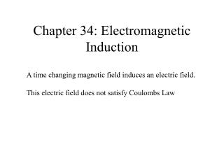
Chapter 31A - Electromagnetic Induction
Chapter 31A - Electromagnetic Induction. A PowerPoint Presentation by Paul E. Tippens, Professor of Physics Southern Polytechnic State University. © 2007. Objectives: After completing this module, you should be able to:.

Chapter 31A - Electromagnetic Induction
E N D
Presentation Transcript
Chapter 31A - Electromagnetic Induction A PowerPoint Presentation by Paul E. Tippens, Professor of Physics Southern Polytechnic State University © 2007
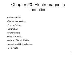
Objectives: After completing this module, you should be able to: • Calculate the magnitude and direction of the induced current or emf in a conductor moving with respect to a given B-field. • Calculate the magnetic flux through an area in a given B-field. • Apply Lenz’s law and the right-hand rule to determine directions of induced emf. • Describe the operation and use of ac and dc generators or motors.
B I Down I Up Down Up v F B B F v Induced Current When a conductor moves across flux lines, magnetic forces on the free electrons induce an electric current. Right-hand force rule shows current outward for down and inward for up motion. (Verify)
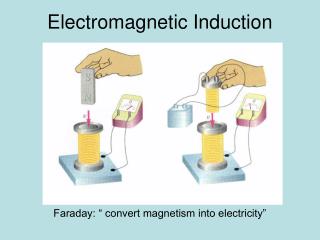
B Faraday’s observations: Flux lines F in Wb N turns; velocityv Faraday’s Law: Induced EMF: Observations • Relative motion induces emf. • Direction of emf depends on direction of motion. • Emf is proportional to rate at which lines are cut (v). • Emfis proportional to the number of turns N. The negative sign means that E opposes its cause.
Df DA Magnetic Flux density: Magnetic Flux Density • Magnetic flux lines Fare continuous and closed. • Direction is that of the B vector at any point. When area A is perpendicular to flux: The unit of flux density is the weber per square meter.
n A q a B Calculating Flux When Area is Not Perpendicular to Field The flux penetrating the area A when the normal vector n makes an angle of q with the B-field is: The angle q is the complement of the angle a that the plane of the area makes with B field. (Cos q = Sin a)
x x x x x x x x x x x x x x x x n n n q A (c)q = 600 A = 40 cm2 (a)q = 00 (b)q = 900 Example 1: A current loop has an area of 40 cm2and is placed in a 3-T B-field at the given angles. Find the fluxF through the loop in each case. (a)F = BA cos 00 = (3 T)(0.004 m2)(1); F = 12.0 mWb (b)F = BA cos 900 = (3 T)(0.004 m2)(0); F = 0 mWb (c)F = BA cos 600 = (3 T)(0.004 m2)(0.5); F = 6.00 mWb
A change in flux DF can occur by a change in area or by a change in the B-field: Faraday’s Law: n n DF = B DA DF = A DB n Rotating loop = B DA Loop at rest = A DB Application of Faraday’s Law
N = 200 turns n q N S B B = 4 mT; 00 to 900 Example 2: A coil has 200 turns of area 30 cm2. It flips from vertical to horizontal position in a time of 0.03 s. What is the induced emf if the constant B-field is 4 mT? DA = 30 cm2 – 0 = 30 cm2 DF = B DA = (3 mT)(30 cm2) DF = (0.004 T)(0.0030 m2) DF = 1.2 x 10⁻⁵ Wb E = -0.080 V The negative sign indicates the polarity of the voltage.
Induced B Induced B Left motion I Right motion N S N S I Lenz’s Law Lenz’s law: An induced current will be in such a direction as to produce a magnetic field that will oppose the motion of the magnetic field that is producing it. Flux increasing to left induces loop flux to the right. Flux decreasing by right move induces loop flux to the left.
R Example 3: Use Lenz’s law to determine direction of induced current through R if switch is closed for circuit below (B increasing). Close switch. Then what is direction of induced current? The rising current in right circuit causes flux to increase to the left, inducing current in left circuit that must produce a rightward field to oppose motion. Hence current I through resistor R is to the right as shown.
I B x x x x x x x x x x x x x x x x x x x x x x x x x x x x x x x x x x x x x x x x x x x x x x x x x x x x x x x x x x x x I v v v x x x x x x x x x x x x x x x x x x I v x B Induced emf Lenz’s law Directions of Forces and EMFs I An emf E is induced by moving wire at velocity v in constant B field. Note direction of I. L From Lenz’s law, we see that a reverse field (out) is created. This field causes a leftward force on the wire that offers resistance to the motion. Use right-hand force rule to show this.
F x x x x x x x x x x x x x x x x x x x x x x x x x x x x x x x x x x x x x x x x x x x x x x B I I L v v B q v sin q v x Induced Emf E Motional EMF in a Wire Force F on chargeqin wire: F = qvB; Work = FL = qvBL EMF: If wire of length L moves with velocity v an angle q with B:
North v q B South North v I B South Example 4:A 0.20-m length of wire moves at a constant speed of 5 m/s in at 1400 with a 0.4-T B-Field. What is the magnitude and direction of the induced emf in the wire? E = -0.257 V Using right-hand rule, point fingers to right, thumb along velocity, and hand pushes in direction of induced emf—to the north in the diagram.
B v I I v B The AC Generator • An alternating AC current is produced by rotating a loop in a constant B-field. Rotating Loop in B-field • Current on left is outward by right-hand rule. • The right segment has an inward current. • When loop is vertical, the current is zero. Iin Ris right, zero, left, and then zero as loop rotates.
Operation of AC Generator I=0 I=0
Rectangular loop a x b n . n a B q B b q b/2 v Area A = ab x v = wr n q B v r = b/2 q x vsin q Calculating Induced EMF Each segment a has constant velocity v. Both segments amoving with v at angle qwith B gives emf:
x . x . +E -E The emf varies sinusoidally with max and min emf Sinusoidal Current of Generator For N turns, the EMF is:
. n B q x f = 60 Hz Example 5:An ac generator has 12 turns of wire of area 0.08 m2. The loop rotates in a magnetic field of 0.3 T at a frequency of 60 Hz. Find the maximum induced emf. w = 2pf = 2p(60Hz) = 377 rad/s Emf is maximum when q = 900. Emax = 109 V The maximum emf generated is therefore: If the resistance is known, then Ohm’s law (V = IR)can be applied to find the maximum induced current.
The simple ac generator can be converted to a dc generator by using a single split-ring commutator to reverse connections twice per revolution. Commutator E t DC Generator The DC Generator For the dc generator: The emf fluctuates in magnitude, but always has the same direction (polarity).
Eb I V Electric Motor The Electric Motor In a simple electric motor, a current loop experiences a torque which produces rotational motion. Such motion induces a back emf to oppose the motion. Applied voltage – back emf = net voltage V – Eb = IR Since back emf Eb increases with rotational frequency, the starting current is high and the operating current is low: Eb = NBAw sin q
Motor Armature and Field Windings In the commercial motor, many coils of wire around the armature will produce a smooth torque. (Note directions of I in wires.) Series-Wound Motor: The field and armature wiring are connected in series. Shunt-Wound Motor: The field windings and the armature windings are connected in parallel.
Eb I V Example 6:A series-wound dc motor has an internal resistance of 3 W. The 120-V supply line draws 4 A when at full speed. What is the emf in the motor and the starting current? V – Eb = IR Recall that: 120 V – Eb = (4 A)(3 W) The back emf in motor: Eb = 108 V The starting current Is is found by noting that Eb= 0 in beginning (armature has not started rotating). Is = 40 A 120 V – 0 = Is (3 W)
A change in flux DF can occur by a change in area or by a change in the B-field: Faraday’s Law: DF = B DA DF = A DB Summary Calculating flux through an area in a B-field:
Induced B Induced B Left motion I Right motion N S N S I Flux increasing to left induces loop flux to the right. Flux decreasing by right move induces loop flux to the left. Summary (Cont.) Lenz’s law: An induced current will be in such a direction as to produce a magnetic field that will oppose the motion of the magnetic field that is producing it.
B q v sin q v Induced Emf E For N turns, the EMF is: Summary (Cont.) An emf is induced by a wire moving with a velocity v at an angle q with a B-field. In general for a coil of N turns of area A rotating with a frequency in a B-field, the generated emf is given by the following relationship:
DC Generator V Electric Motor Summary (Cont.) The ac generator is shown to the right. The dc generator and a dc motor are shown below:
Motor Summary (Cont.) The rotor generates a back emf in the operation of a motor that reduces the applied voltage. The following relationship exists: Applied voltage – back emf = net voltage V – Eb = IR