Download
1 / 68
770 likes | 2.24k Vues
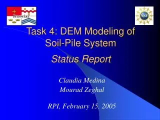
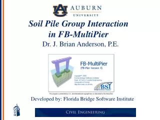
Dr. J. Brian Anderson, P.E. Soil-Pile Interaction in FB-MultiPier. Developed by: Florida Bridge Software Institute Dr. Mike McVay, Dr. Marc Hoit, Dr. Mark Williams. Session Outline. Identify and Discuss Soil-Pile Interaction Models Precast & Cast Insitu Axial T-Z & Q-Z Models

E N D
Dr. J. Brian Anderson, P.E. Soil-Pile Interaction in FB-MultiPier Developed by: Florida Bridge Software Institute Dr. Mike McVay, Dr. Marc Hoit, Dr. Mark Williams
Session Outline • Identify and Discuss Soil-Pile Interaction Models • Precast & Cast Insitu Axial T-Z & Q-Z Models • Torsional T- Models • Lateral P-Y Models • Nonlinear Pile Structural Models • FB-MultiPier Input and Output • Example #1 Single Pile
Session Outline • Identify and Discuss Soil-Pile Interaction Models • Precast & Cast Insitu Axial T-Z & Q-Z Models • Torsional T- Models • Lateral P-Y Models • Nonlinear Pile Structural Models • FB-MultiPier Input and Output • Example #1 Single Pile
Soil-Structure Interaction Vertical Nonlinear Spring Torsional Nonlinear Spring Lateral Nonlinear Spring Nonlinear Tip Spring
z s + / r r D t D · d q t s + D s / D r · d r r r z d s r t s q dr d q r Driven Piles - Axial Side Model z r to (Randolph & Wroth) s
Driven Piles - Axial Side Model r0 rm Also: Z z Substitute: r Rearrange: Previous Substitute: Also: Substitute:
Driven Piles - Axial Side Model f = 1000psf Gi = 3 ksi
Driven Piles - Axial Tip Model (Kraft, Wroth, etc.) Where: P = Mobilized Base Load Pf = Failure Tip Load ro = effective pile radius = Poisson ratio of Soil Gi = Shear Modulus of Soil Pf = 250 kips Gi = 10 ksi = 0.3 r0 = 12 inches
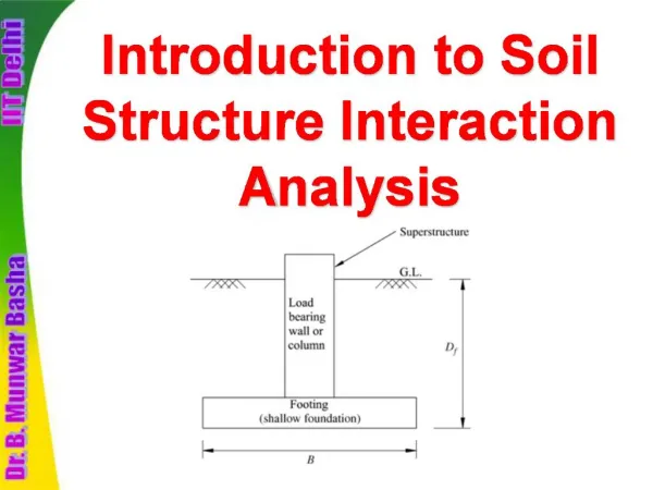
Driven Piles - Axial Properties • Ultimate Skin Friction (stress), Tauf, along side of pile (input in layers). • Ultimate Tip Resistance (Force), Pf, at pile tip . • Compressibility of individual soil layers, I.e. Shear Modulus, Gi, and Poisson’s ratio, n .
Driven Piles - Axial Properties • From Insitu Data: • Using SPT “N” Values run SPT97, DRIVEN, UNIPILE, etc. to Obtain: Tauf , and Pf • Using Electric Cone Data run PL-AID, LPC, FHWA etc. to Obtain: Tauf , and Pf • Determine G or E from SPT correlations, i.e. Mayne, O’Neill, etc.
Skin Friction, tf (TSF) Plastic Clay: f= 2N(110-N)/4006 Sand, Silt Clay Mix: f = 2N(110-N)/4583 Clean Sand: f = 0.019N Soft Limestone f = 0.01N Florida: SPT 97 Concrete Piles • Ultimate Tip, Pf/Area(tsf) • Plastic Clay: • q = 0.7 N • Sand, Silt Clay Mix: • q = 1.6 N • Clean Sand: • q = 3.2 N • Soft Limestone • q = 3.6 N
Cast Insitu Axial Side and Tip Models • For soil (sands and clays) • Follow FHWA Drilled Shaft Manual For Sands and Clays to Obtain Tauf and Pf (g and cu) • Shape of T-Z cuve is given by FHWA’s Trend Lines. • User has Option of inputting custom T-z / Q-z curves
Cast Insitu - Sand (FHWA): L/2 sv’ = g L/2 L b = 1.5 -.135 (L/2) 0.5 1.2> b >0.25 D Qs = p D L b sv’ Qt = 0.6 NSPTp D 2 / 4 NSPT < 75
Cast Insitu - Clay (FHWA): Qs = 0.55 Cu p D (L-5’-D) L D Qt = 6 [1+0.2(L/D) ] Cu (p D 2 / 4)
Session Outline • Identify and Discuss Soil-Pile Interaction Models • Precast & Cast Insitu Axial T-Z & Q-Z Models • Torsional T- Models • Lateral P-Y Models • Nonlinear Pile Structural Models • FB-MultiPier Input and Output • Example #1 Single Pile
Torsional Model (Pile/Shaft) • Hyperbolic Model • G and Tauf • Custom T-q
Torsional Model (Pile/Shaft) T (F-L) (dT/dq)=1/a Gi Tult =1/b Tult = f Asurfr Tult = 2p r2 D L tult T = q / ( a + b q ) ult = Ultimate Axial Skin Friction (stress) q (rad)
Session Outline • Identify and Discuss Soil-Pile Interaction Models • Precast & Cast Insitu Axial T-Z & Q-Z Models • Torsional T- Models • Lateral P-Y Models • Nonlinear Pile Structural Models • FB-MultiPier Input and Output • Example #1 Single Pile
Lateral Soil-Structure Interaction Y Active State Passive State
P x = x4 x = x3 x = x2 u p u x = x1 m m yu p m k y m p k y k ks x x = 0 3b/80 b/60 y P-y Curves - Reese’s Sand Pu is a function of , , and b Y is a function of b (pile diameter)
Matlock’s Soft Clay Pu is a function of Cu, , and b Y is a function of y50 (50)
Reese’s Stiff Clay Below Water Pc is a function of C, , ks and b Y is a function of y50 (50)
O’Neill’s Integrated Clay Pu is a function of c, and b Fs is a function of 100 Yc is a function of b and 50
Soil Properties for Standard Curves • Sand: • Angle of internal friction, f • Total unit weight, g • Modulus of Subgrade Reaction, k • Clay or Rock: • Undrained Strength, Cu • Total Unit Weight, g • Strain at 50% of Failure Stress, e50 • Optional: k, ande100
Soil Information Help Menu EPRI (Kulhawy & Mayne)
P-y Curves from Insitu Tests • Cone Pressuremeter • Marchetti Dilatometer
Cone Pressuremeter (Robertson, Briaud, etc.)
4500 4000 3500 DMT 3000 2500 Load (kN) 2000 PMT 1500 1000 Actual 500 0 0 10 20 30 40 50 Deflection (mm) Pascagoula Predictions
Instrumentation & Measurements • Strain gages • Measure strain • Calculate bending moment, M = ε(EI/c), if EI of section known • “high tech” • Slope inclinometer • Measures slope • Relatively “low tech”